Radiofrequency ablation control system

A technology of radiofrequency ablation and control system, applied in the field of radiofrequency ablation of atrial fibrillation, can solve the problems of inability to prompt, inaccurate estimation of ablation energy and effect, and distraction of attention for the operation of ablation catheter, so as to improve the success rate and safety, and avoid ablation Insufficient degree to avoid the effect of excessive ablation

Active Publication Date: 2020-10-16
成都市第三人民医院
View PDF7 Cites 1 Cited by
  • Summary
  • Abstract
  • Description
  • Claims
  • Application Information

AI Technical Summary

Problems solved by technology

However, such technical indicators only consider the pressure, power and time factors of the ablation catheter, and the individualized anatomical information (such as heart location, thickness, movement, etc.), impedance, (esophageal) temperature, local voltage, and respiratory rate of the target. Important electrophysiological indicators such as mobility are not considered, so the estimation of the released ablation energy and effect is not accurate; more importantly, these technical indicators only indicate the released ablation energy, and the ablation energy that should be released for the target The size of the energy cannot be prompted, nor can it be prompted which parameter combination should be used to provide the corresponding energy. At the same time, the process of ablation energy release cannot be automatically controlled. The operator still needs to rely on experience to pay attention to and control the aforementioned various Electrophysiological indicators to allow manual control of the ablation energy delivery process, thereby distracting attention from the ablation catheter operation itself

Method used


Image

  • Radiofrequency ablation control system
  • Radiofrequency ablation control system
  • Radiofrequency ablation control system

Examples


Embodiment Construction

[0023] The present invention will be further described below in conjunction with specific drawings and embodiments.

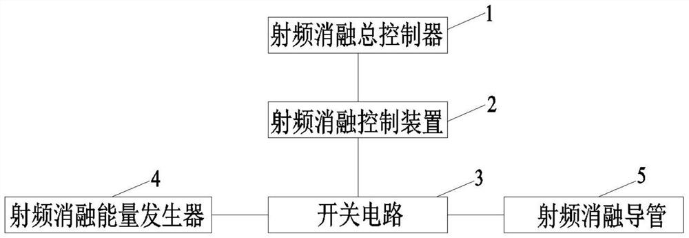
[0024] Such as figure 1 and figure 2 As shown: as an example, it can effectively realize the transmural damage of the target point, which is conducive to the formation of continuous ablation lesions, and effectively improves the success rate and safety of atrial fibrillation ablation surgery. The present invention includes a radio frequency ablation energy generator 4 and the radio frequency A radiofrequency ablation catheter 5 adapted to the ablation energy generator 4, the radiofrequency ablation energy generator 4 is connected to the radiofrequency ablation catheter 5 through a switch circuit 3, and the switch circuit 3 is electrically connected to the radiofrequency ablation control device 2;

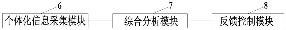
[0025] The radio frequency ablation control device 2 includes an individualized information collection module 6 for collecting individualized ablation information,...


PUM


Abstract

The invention relates to a radiofrequency ablation control system which comprises a radiofrequency ablation energy generator; the radiofrequency ablation energy generator is connected with a radiofrequency ablation catheter through a switching circuit, and the switching circuit is electrically connected with a radiofrequency ablation control device; the radiofrequency ablation control device comprises an individualized information acquisition module, a comprehensive analysis module and a feedback control module; the comprehensive analysis module can obtain actual radio frequency conduction time T of a target spot according to individualized ablation information acquired by the individualized information acquisition module and an initial value corresponding to the individualized ablation information; and a feedback control module can control the on-off state of the switching circuit according to the target spot time radio frequency conduction time T, and thus control the radiofrequencyablation state of the radiofrequency ablation catheter to the target spot. According to the invention, transmural injury of the target spot can be effectively realized, formation of a continuous ablation lesion is facilitated, and the success rate and the safety of atrial fibrillation ablation operation are effectively improved.

Description

technical field [0001] The invention relates to a control system, in particular to a radio frequency ablation control system, which belongs to the technical field of atrial fibrillation radio frequency ablation. Background technique [0002] At present, cardiac radiofrequency ablation has been widely carried out in the field of treating arrhythmia diseases. The key to radiofrequency ablation of complex arrhythmias is to form a continuous linear, transmural, and safe ablation lesion, such as the common ring pulmonary vein electrical isolation in atrial fibrillation ablation, which aims to form a continuous linear transmural ablation lesion around the pulmonary vein to ensure There is no electrical connection with the left atrium, and the extended application of matrix modification on this basis. Therefore, in radiofrequency ablation of the heart, whether transmural cell necrosis occurs in the tissue at the ablation site is the key to the success of a single radiofrequency ab...

Claims


Application Information

Patent Timeline
Patent Type & Authority Applications(China)
IPC IPC(8): A61B18/12A61B18/14
CPCA61B18/12A61B18/1206A61B18/1492A61B2018/00702A61B2018/00577A61B2018/00875A61B2018/00892
Inventor 刘汉雄
Owner 成都市第三人民医院
Why Eureka
Try Eureka