Eureka AIR delivers breakthrough ideas for toughest innovation challenges, trusted by R&D personnel around the world.

Roll bending forming machine

A forming machine and rolling bending technology, applied in heat exchange equipment and other directions, can solve problems such as poor practicability, time-consuming, labor-intensive, dangerous, etc., achieve the effect of good transportation, avoid close operation, and improve safety

Inactive Publication Date: 2020-10-13
NANTONG CHAOLI ROLLING MACHINE PRODUCING
View PDF0 Cites 0 Cited by
  • Summary
  • Abstract
  • Description
  • Claims
  • Application Information

AI Technical Summary

Problems solved by technology

The hot water or steam generated in the boiler can directly provide the required thermal energy for industrial production and people's life, and can also be converted into mechanical energy through a steam power plant, or converted into electrical energy through a generator. Too high will cause danger. Generally, the outer wall of the boiler is equipped with a spiral coil radiator. The radiator of the spiral coil is generally made by a roll forming machine; The final coil is generally stabilized by hand, and transported away by a crane. The hook of the crane needs to be hooked manually. This process is time-consuming and laborious, and there are certain risks, so the practicability is poor.

Method used


Image

  • Roll bending forming machine
  • Roll bending forming machine
  • Roll bending forming machine

Examples


Embodiment Construction

[0019] The following will clearly and completely describe the technical solutions in the embodiments of the application with reference to the drawings in the embodiments of the application. Apparently, the described embodiments are only some of the embodiments of the application, not all of them. Based on the embodiments in this application, all other embodiments obtained by persons of ordinary skill in the art without making creative efforts belong to the scope of protection of this application.

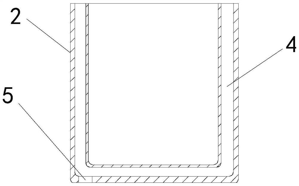
[0020] see Figure 1-3 , a rolling forming machine of the present application, including a base 91, an annular barrel 2 and a clamping mechanism, a rolling mechanism and a support frame 3 are installed on the top of the base 91, and the support frame 3 is located outside the rolling mechanism , the annular barrel 2 is installed on the top of the support frame 3, the top of the annular barrel 2 is provided with an annular groove 4, and the inner bottom wall of the annular groove 4 is...


PUM


Abstract

The invention relates to the technical field of roll bending forming, in particular to a roll bending forming machine. The roll bending forming machine is used for limiting and fixing a formed bent pipe, reducing transportation of a coiled pipe by manual operation, saving time and labor and improving practicability. The roll bending forming machine comprises a base, an annular barrel and a clamping mechanism, a roll bending mechanism and a supporting frame are installed at the top end of the base, the supporting frame is located on the outer side of the roll bending mechanism, the annular barrel is installed at the top end of the supporting frame, an annular groove is formed in the top end of the annular barrel, a pipe inlet is formed in the inner bottom wall of the annular groove and is opposite to the output end of the roll bending mechanism, through holes are formed in the front end and the rear end of the annular barrel, the clamping mechanism is located above the annular barrel and comprises a conveying frame, a threaded rod, a rotating motor and a moving seat, a groove is formed in the bottom end of the conveying frame, the left end of the threaded rod is connected with the left side wall of the groove through a bearing, the right end of the threaded rod extends out of the groove to be connected with the output end of the rotating motor, and a threaded hole is formed in the top of the left end of the base.

Description

technical field [0001] The present application relates to the technical field of roll bending, in particular to a roll forming machine. Background technique [0002] As we all know, a boiler is a kind of energy conversion equipment. The energy input to the boiler includes chemical energy and electric energy in the fuel, and the boiler outputs steam, high-temperature water or organic heat carrier with a certain amount of heat energy. The water container, the furnace refers to the place where fuel is burned, and the boiler includes two parts: the pot and the furnace. The hot water or steam generated in the boiler can directly provide the required thermal energy for industrial production and people's life, and can also be converted into mechanical energy through a steam power plant, or converted into electrical energy through a generator. Too high will cause danger. Generally, the outer wall of the boiler is equipped with a spiral coil radiator. The radiator of the spiral coil...

Claims


Application Information

Patent Timeline
Patent Type & Authority Applications(China)
IPC IPC(8): B21D11/06B21D11/22B21D53/06
CPCB21D11/06B21D11/22B21D53/06
Inventor 李森林唐子钦赵非平
Owner NANTONG CHAOLI ROLLING MACHINE PRODUCING
Why Eureka
Eureka Blog
Learn More