
Installation structure of imaging laser radar

A technology of laser radar and installation structure, which is applied in the direction of instruments, radio wave measurement systems, supporting machines, etc., can solve problems such as large assembly errors, complex integrated assembly installation, imaging quality and accuracy, and achieve weight reduction and small and compact structure , Stable and reliable imaging effect

Pending Publication Date: 2020-10-09
江西上科极星光电技术有限公司
View PDF0 Cites 0 Cited by
  • Summary
  • Abstract
  • Description
  • Claims
  • Application Information

AI Technical Summary

Problems solved by technology

It can be hand-held or integrated with other equipment, but the integrated assembly and installation of the equipment is complicated, the assembly error is large, and the imaging quality and accuracy are affected to a certain extent

Method used


Image

  • Installation structure of imaging laser radar
  • Installation structure of imaging laser radar

Examples


Embodiment Construction

[0019] The present invention will be further described in detail below in conjunction with the accompanying drawings and specific embodiments. According to the following description, the purpose, technical solution and advantages of the present invention will be more clear. It should be noted that the described embodiments are preferred embodiments of the present invention, but not all embodiments.

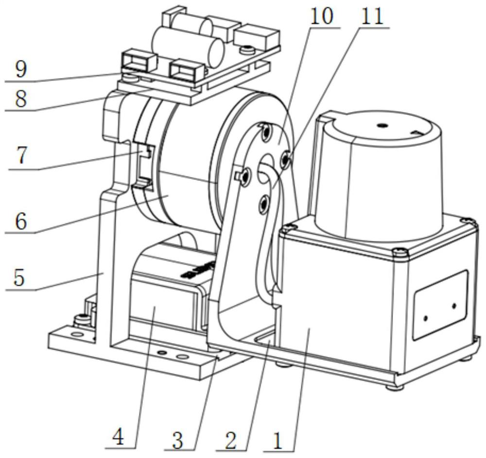
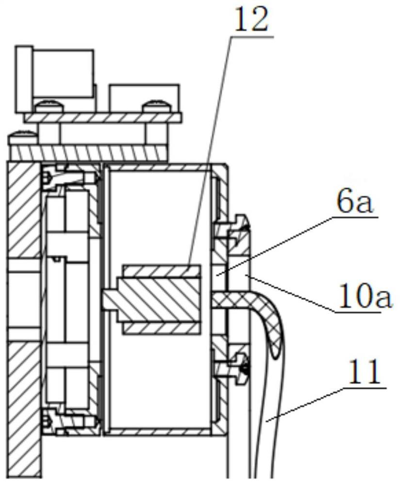
[0020] combine figure 1 with figure 2 As shown, an imaging laser radar installation structure includes a base plate 12 , a motor fixing frame 5 vertically fixed on the base plate 12 and an L-shaped radar mounting bracket 10 . In order to ensure that the motor mounting surface is perpendicular to the plane of the fixing frame and reduce processing costs, the bottom plate 12 and the motor fixing frame 5 are integrally formed.

[0021] A hollow servomotor 6 is installed on one side of the motor fixing frame 5, and a conductive slip ring 13 is installed in the hollow position of t...


PUM


Abstract

The invention relates to an installation structure of imaging laser radar. The installation structure comprises a bottom plate, a motor fixing frame vertically and fixedly arranged on the bottom plateand an L-shaped radar installation support. A hollow servo motor is mounted on one side of the motor fixing frame; a conductive slip ring is mounted in the hollow position of the servo motor; a navigation gyroscope is mounted in the middle of the bottom plate; the top end of the motor fixing frame is fixedly connected with a motor control installation plate, a motor control panel is installed onthe motor control installation plate, a positioning clamping groove is formed in the horizontal section of the radar installation support, the laser radar is installed in the positioning clamping groove, and the vertical section of the radar installation support is installed on the end face of the servo motor. The conductive slip ring is installed in the hollow part of the servo motor, and the motor control panel is installed on the motor control installation plate, so that the structure is small and compact, the overall weight is reduced, and installation and carrying are convenient. Due to the arrangement of a positioning groove and the positioning clamping groove, assembly is convenient, installation errors are reduced, and installation precision is guaranteed.

Description

technical field [0001] The invention relates to an installation structure of imaging laser radar, belonging to the technical field of imaging laser radar installation. Background technique [0002] LiDAR is an active detection technology that can accurately and quickly obtain three-dimensional space information of targets. It has unique technical advantages in target recognition, classification, and high-precision three-dimensional imaging and measurement. Its application scope and development prospects are very broad. At present, the application of lidar has developed from ground to air, from air to space, from land to sea, from sea to underwater, and involves many disciplines. [0003] Imaging lidar is a new technology product that integrates various technologies such as laser technology, radar technology, optical scanning, control technology, high-sensitivity detection technology and high-speed computer processing technology. As an important part of the imaging system, t...

Claims


Application Information

Patent Timeline
Patent Type & Authority Applications(China)
IPC IPC(8): G01S7/481F16M11/06F16M11/18
CPCG01S7/481F16M11/06F16M11/18
Inventor 罗海燕王丽袁山山董添董岿然
Owner 江西上科极星光电技术有限公司
Learn More