
Fabricated energy dissipation and vibration reduction wall slab structure and construction method thereof

A prefabricated and wall panel technology, applied in the direction of walls, earthquake resistance, building components, etc., can solve problems such as inability to assemble, and achieve the effects of increased pressure, energy consumption, reliable connection, and extended durability

Pending Publication Date: 2020-10-09
HUNAN UNIV
View PDF1 Cites 4 Cited by
  • Summary
  • Abstract
  • Description
  • Claims
  • Application Information

AI Technical Summary

Problems solved by technology

[0004] According to the deficiencies of the above-mentioned prior art, the present invention provides an assembled energy-dissipating and shock-absorbing wall panel structure and its construction method. In addition, it can be limited and reset at the same time, to prevent out-of-plane instability and torsional damage of the wallboard; it can be spliced ​​with various dampers for energy consumption; it can prevent the thread from loosening and increase Durable; does not produce additional rigidity to the structure, and the force is clear, protecting the prefabricated wall panels

Method used


Image

  • Fabricated energy dissipation and vibration reduction wall slab structure and construction method thereof
  • Fabricated energy dissipation and vibration reduction wall slab structure and construction method thereof
  • Fabricated energy dissipation and vibration reduction wall slab structure and construction method thereof

Examples


Embodiment 1

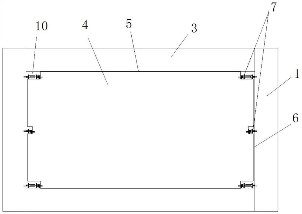
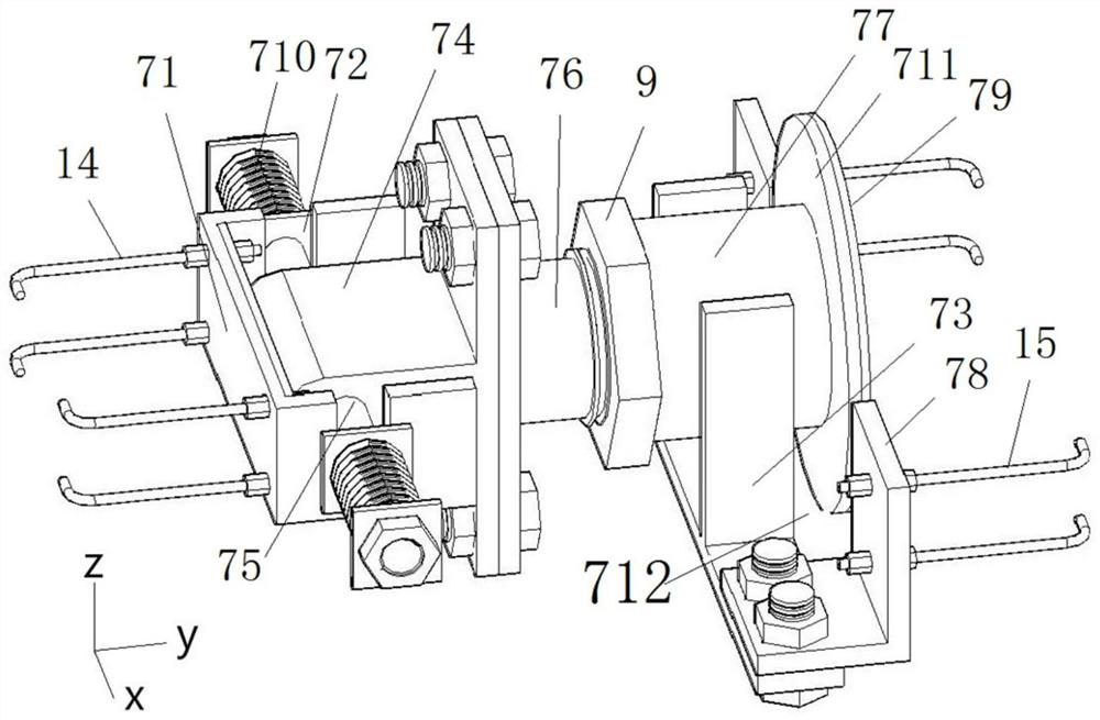
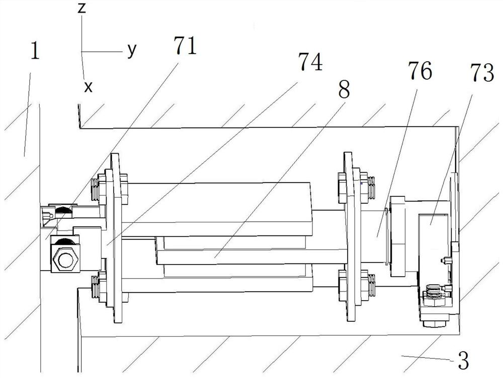
[0056] Such as Figure 1-8 As shown, it includes a frame composed of frame columns 1 and frame beams 3 and a wall panel structure inside the frame. In this embodiment, the frame is a concrete frame with a span of 5400mm and a floor height of 3000mm. The cross-sectional dimensions of the left and right frame columns are both 500mm×500mm, and the cross-sectional dimensions of the top and bottom beams are both 300mm×500mm. The design strength of the concrete The grade is C30. The reinforcement of beams and columns is determined according to "Code for Design of Concrete Structures" (GB50010-2010) and "Code for Seismic Design of Buildings" (GB50011-2010).

[0057] A damping layer 5 is installed between the wall panel 4 and the frame beam 3; a flexible filler 6 is filled between the wall panel 4 and the frame column 1;

[0058] The flexible filler 6 is a PU foaming agent.

[0059] The connecting structure 7 includes a pre-embedded fixture and a connecting piece; the pre-embedded ...

Embodiment 2

[0075] On the basis of Example 1, in order to further increase the anti-seismic finishing of the wall panels, the following improvements are made: flexible fillers 6 are filled between the wall panels 4 and the frame beams and frame columns.

[0076] Wallboard 4 is a rectangular wallboard, and the rectangular wallboard includes two L-shaped sub-wallboards 41 of the same size and shape; the two L-shaped sub-wallboards 41 are rotationally symmetrically arranged with the geometric center of the rectangular wallboard; The horizontal contact interface of the sub-wall panel 41 is on both sides of the wall panel 4, and the horizontal contact interface is filled with a damping layer 5, and is connected to each other through the in-plane bending deformation energy dissipator 19 of the steel plate; the two L-shaped sub-wall panels 41 The vertical contact interface is in the middle of the wallboard 4, and the impact buffer layer 18 is fixed at the vertical contact interface, and the flexi...


PUM


Abstract

The invention discloses a fabricated energy dissipation and vibration reduction wall slab structure and a construction method thereof. The wall slab structure comprises frame columns on the left sideand the right side, and the upper parts and the lower parts of the two frame columns are connected through frame beams respectively; an enclosed space for installing a wall slab is formed by the framecolumns and the frame beams in an enclosing manner; a damping layer is mounted between the wall slab and the frame beams; the portion between the wall slab and the frame columns is filled with a flexible filler; and the left and right ends of the wall slab are rotatably connected with the frame columns through connecting structures 7. According to the fabricated energy dissipation and vibration reduction wall slab structure, the frame columns are rotatably connected with the wall slab, so that in the case of an earthquake, the wall slab can be twisted when the frame columns are twisted or deformed, and damage to the wall slab caused by twisting of the frame columns during vibration is avoided; and moreover, fixing parts and the connecting parts are pre-embedded to realize the quick connection and installation of the frame columns and the wall slab, and the wall slab structure can adapt to the installation error of each angle.

Description

technical field [0001] The invention relates to the technical field of buildings, in particular to an assembled energy-dissipating and shock-absorbing wallboard structure. Background technique [0002] In construction engineering, frame structures are widely used. The plane layout of the frame structure is flexible, and the beams, columns, and floor components of the frame structure are easy to standardize, and it is convenient to adopt the assembly method for construction. However, due to the small lateral stiffness of the frame structure, earthquakes are likely to cause excessive deformation response of the structure. Due to the complex interaction between the traditional masonry infill wall and the frame structure, the masonry infill wall itself has poor deformation ability and integrity. When encountering an earthquake, the failure of the masonry infill wall is more common and will cause frame beams and columns Component damage occurs. These problems put forward new r...

Claims


Application Information

Patent Timeline
IPC IPC(8): E04B2/74E04B2/82E04B1/98E04H9/02
CPCE04B2/74E04B2/82E04B1/98E04H9/021E04B2002/7461E04B2002/7477
Inventor 马高张博鸿
Owner HUNAN UNIV
Learn More