
Trailing suction dredger with outer rotor motor driven hob head

A technology of external rotor motor and trailing suction dredger, which is applied to mechanically driven excavators/dredgers, earth movers/shovels, construction, etc. Problems such as head work efficiency, failure to achieve expected work efficiency, etc.

Active Publication Date: 2022-04-26
NAT ENG RES CENT OF DREDGING TECH & EQUIP
View PDF0 Cites 0 Cited by
  • Summary
  • Abstract
  • Description
  • Claims
  • Application Information

AI Technical Summary

Problems solved by technology

In addition, the shaft diameter of the driving system with this driving capacity is larger than the diameter of the drum with rake teeth, which makes it difficult for the rake teeth to cut into or cut medium hard soil, the dredging efficiency is limited, and the expected operating efficiency cannot be achieved
[0007] (2) A larger drive system will also cause the support structure connected to the drum shaft to account for a larger proportion of the horizontal axis of the drum, and the actual width of the hob involved in cutting only accounts for 50% to 60% of the design size of the horizontal axis of the drum, reducing the Improve the operating efficiency of the hob harrow head
[0010] It can be seen that a well-designed reducer must make the gearbox occupy the horizontal axial dimension of the drum, resulting in reduced excavation efficiency
[0011] (3) The equipment technology of underwater reducers in the range of 20-60m in water depth is still immature, and there are no serialized products to choose from. It is very difficult to control the reliability of customized products and the supply link, and the frequency of fault maintenance in the use link will also increase. multiplied
[0012] Therefore, it is necessary to design a new type of trailing suction dredger, whose rake head can improve the soil breaking ability and construction efficiency of the trailing suction dredger, so as to solve the problem of operating efficiency of hard soil dredging

Method used


Image

  • Trailing suction dredger with outer rotor motor driven hob head
  • Trailing suction dredger with outer rotor motor driven hob head
  • Trailing suction dredger with outer rotor motor driven hob head

Examples


Embodiment Construction

[0040] The present invention will be further described below in conjunction with accompanying drawing and embodiment, but present embodiment is not intended to limit the present invention, and all adopt similar structures of the present invention and similar changes thereof, all should be included in the scope of protection of the present invention.

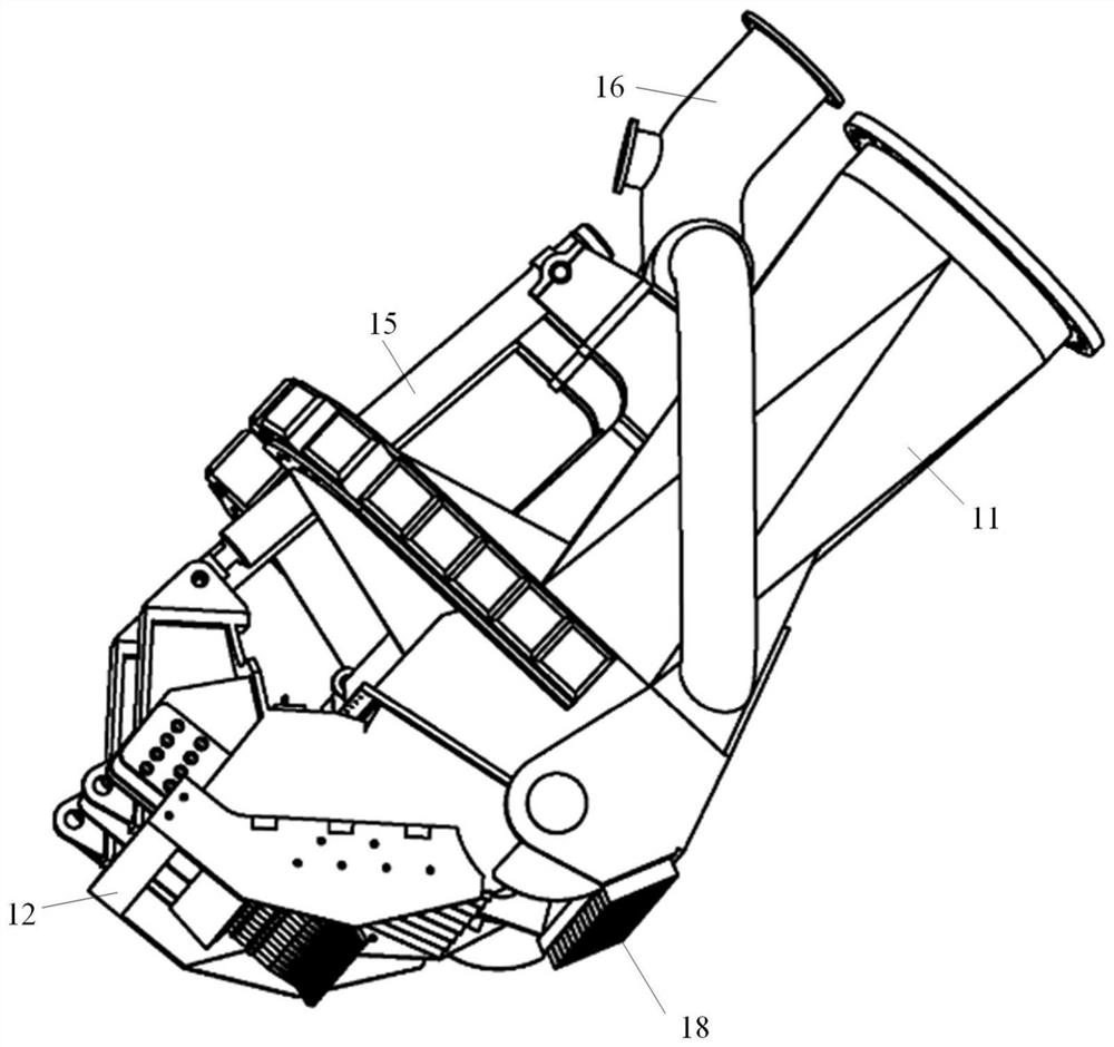
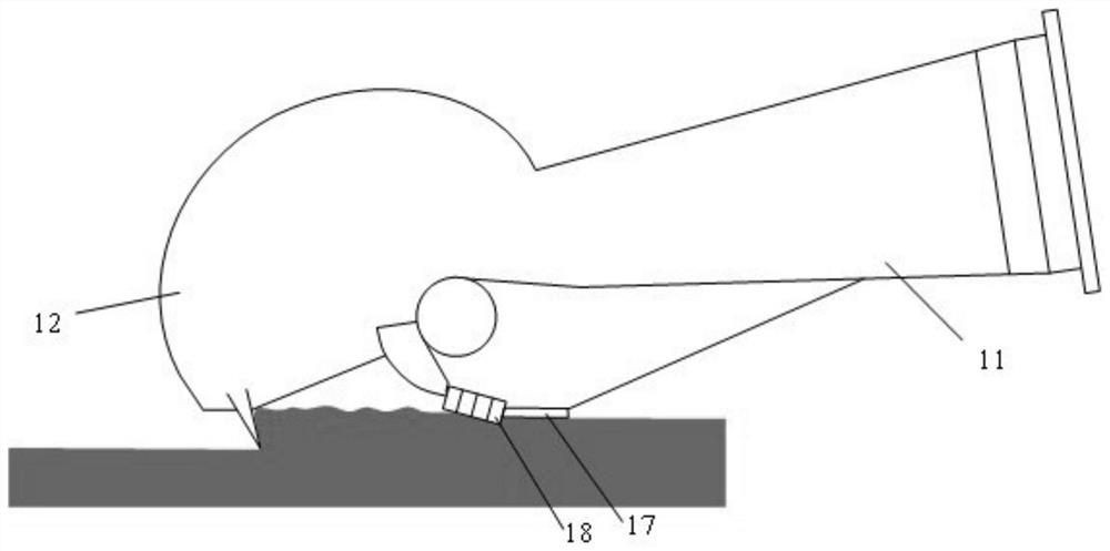
[0041] A trailing suction dredger with a hob rake head driven by an external rotor motor includes a rake head 1 connected to a hull 3 through a rake arm. Such as Figure 5-7 The hob rake head shown includes: rake head fixed body 11, rake head movable cover 12, drum 13 with rake teeth, outer rotor motor 14, hydraulic device 15, high-pressure flushing elbow 16, rake head movable cover 12 and rake head fixed body 11, the cylinder 13 that rake teeth are housed, hydraulic unit 15 are all movably connected. The rake head fixed body 11 is movably connected with the rake head movable cover 12 through pin holes; the roller 13 equipped wi...


PUM


Abstract

The invention provides a trailing suction dredger with a hob head driven by an external rotor motor. It includes: the hob harrow head, which is connected to the hull through the harrow arm, and the hob harrow head includes a harrow head fixed body, a harrow head movable cover, a drum equipped with harrow teeth, an external rotor motor, and a hydraulic device and high-pressure flushing elbow; the rake head fixed body is rotatably connected with the movable cover, and a high-pressure flushing elbow is installed above; the roller with rake teeth is installed under the movable cover, including the roller, tooth seat and rake teeth, and the roller is sealed There is an external rotor motor built into the ground, which drives the drum to rotate around the horizontal axis through the stator and rotor; the entire drum with rake teeth is rotatably connected to the movable cover of the rake head, and can rotate within a certain angle range with the movable cover relative to the fixed body of the rake head. The trailing suction dredger provided by the present invention can effectively control the weight of the rake head, reduce the axial restraint attachment, and increase the effective cutting width, thereby greatly improving the soil-breaking ability of the rake head of the dredger and the operation efficiency of dredging hard soil .

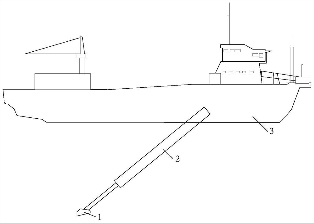
Description

technical field [0001] The invention belongs to the technical field of trailing suction dredgers used in dredging engineering construction operations, and in particular relates to a trailing suction dredger with a hob head driven by an external rotor motor and its use in deep water hard Dredging method for soil cutting. Background technique [0002] Trailing suction dredgers and cutter suction dredgers are the two most widely used dredging construction ships. Among them, the trailing suction dredger is flexible, strong in wind and wave resistance, and has a wide range of operating water depths. During operation, the rake head connected to it is put into the water through the rake arm, and the ship sails through the rake arm to drag the rake head to cut the soil layer. The dredged material is sucked into the fixed body of the rake head and transported to the mud hopper by the rake pipe in the rake arm. [0003] figure 1 Shown is a schematic diagram of the main components o...

Claims


Application Information

Patent Timeline
Patent Type & Authority Patents(China)
IPC IPC(8): E02F5/28E02F3/88E02F3/90E02F3/92
CPCE02F5/282E02F3/8841E02F3/885E02F3/905E02F3/9237
Inventor 尹立明洪国军冒小丹江帅王费新张晴波刘若元树伟陆寅松周忠玮舒敏骅刘功勋张忱李威张露
Owner NAT ENG RES CENT OF DREDGING TECH & EQUIP
Learn More