A gasification device with a spray structure
A technology of gasification equipment and gasifier, which is applied in the field of LNG gasification, and can solve the problems of low heat exchange efficiency and insufficient heat exchange
- Summary
- Abstract
- Description
- Claims
- Application Information
AI Technical Summary
Problems solved by technology
Method used
Image
Examples
Embodiment 1
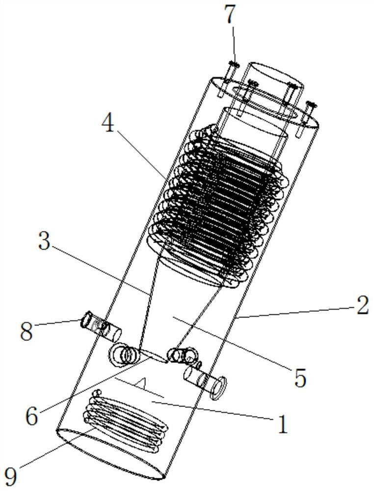
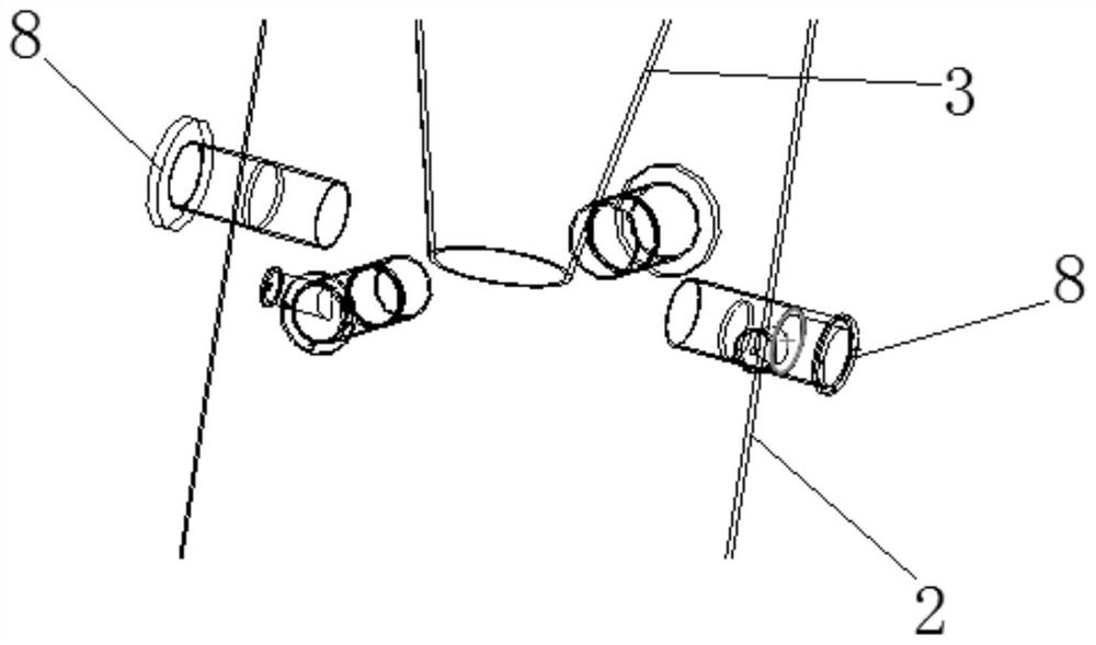
[0032] In order to solve the problem of insufficient heat and moisture exchange between flue gas and water in the original gasifier, this embodiment adopts the spray humidification method, and adopts the multi-nozzle top and middle mode to reduce the energy consumption of the fan and increase the heat exchange efficiency. The structure of gasification equipment is as follows Figure 1 to Figure 3 shown.
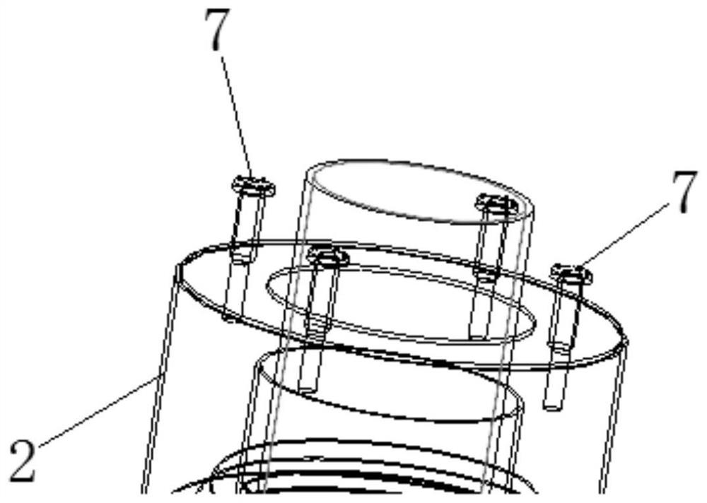
[0033] First, four overhead nozzles 7 are arranged on the top of the gasifier. The water source of the overhead nozzles 7 comes from the bottom pool 1, and the temperature of the water in the bottom pool 1 rises due to the heating of the high-temperature flue gas. The circulation pipe 9 reaches the overhead nozzle 7 and sprays out from the overhead nozzle 7. The multi-nozzle overhead method is used to effectively use the space on the top of the gasifier and improve the utilization rate, and the number of spray structures should not be too large. When the number of nozzles is...
Embodiment 2
[0038] Such as figure 1 A gasification device with a spray structure is shown, including a gasifier body, an overhead nozzle mechanism set on the top of the gasifier body, and a middle nozzle mechanism set on the side of the gasifier body. The gasifier body The interior of the tank is provided with a bottom pool 1, and the overhead nozzle mechanism and the middle nozzle mechanism communicate with the bottom pool 1 respectively.
[0039] Wherein, the gasifier body includes an outer cylinder body 2, a fire tube 3 arranged inside the outer cylinder body 2 and above the bottom pool 1, and a heated tube bundle 4 surrounding the outside of the fire tube 3. A combustion chamber 5 is provided inside the fire tube 3. The heated tube bundle 4 is an upward coiled tube. The torch 3 is arranged vertically, and the bottom of the torch 3 is provided with a flue gas outlet 6 adapted to the bottom pool 1 .
[0040] Such as figure 2 As shown, the overhead nozzle mechanism includes a plurali...
PUM
 Abstract
Description
Claims
Application Information
 - R&D Engineer
- R&D Manager
- IP Professional
- Industry Leading Data Capabilities
- Powerful AI technology
- Patent DNA Extraction
Browse by: Latest US Patents, China's latest patents, Technical Efficacy Thesaurus, Application Domain, Technology Topic, Popular Technical Reports.
© 2024 PatSnap. All rights reserved.Legal|Privacy policy|Modern Slavery Act Transparency Statement|Sitemap|About US| Contact US: help@patsnap.com


