Solid fuel spiral dry distillation machine

A solid fuel, dry distillation machine technology, applied in the direction of biofuel, special form dry distillation, indirect heating dry distillation, etc., can solve the problems of uneven heating of fuel, large fuel processing capacity of dry distillation furnace, reduce carbon production and other problems, and improve energy utilization efficiency. , The material is heated quickly, and the effect of the heating surface of the fuel is improved.

Active Publication Date: 2020-10-09
安徽林农时代科技有限公司
View PDF5 Cites 0 Cited by
  • Summary
  • Abstract
  • Description
  • Claims
  • Application Information

AI Technical Summary

Problems solved by technology

On the basis of the traditional dry distillation reactor, the vertical biomass carbonization device creatively designs a rotary sealing device for feeding and carbon discharge. This device reduces energy consumption, but the fuel naturally hangs down in the carbonization cylinder, and the small diameter of the carbonization cylinder results in a large output. Underneath, the fuel with a large diameter of the retort cylinder is heated unevenly, and the fuel remains in the retort cylinder for a long time, which reduces the carbon production
[0003] Horizontal biomass retort device, the retort cylinder is inclined 3 to 5° relative to the horizontal foundation, multiple hot air pipes are designed parallel to the inner circumference of the retort cylinder, hot air boxes are designed at both ends of the retort cylinder, and the rack surrounding the retort cylinder is connected to the drive gear. Rotating under the action of t

Method used


Image

  • Solid fuel spiral dry distillation machine
  • Solid fuel spiral dry distillation machine
  • Solid fuel spiral dry distillation machine

Examples


Example Embodiment

[0046] In order to describe in detail the technical content, structural features, achieved objectives and effects of the technical solution, the following detailed descriptions are given in conjunction with specific embodiments and accompanying drawings.

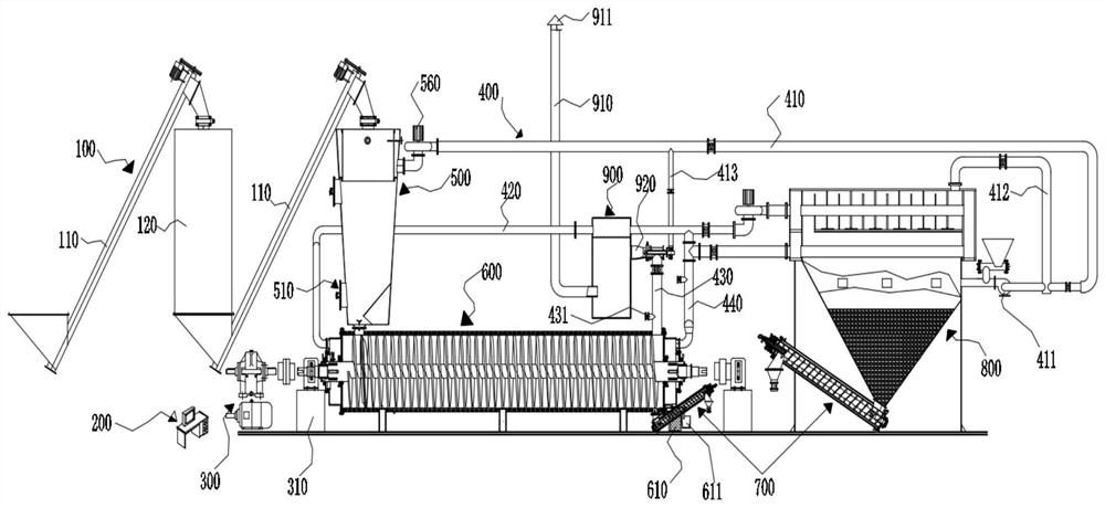
[0047] See figure 1 In this embodiment, a solid fuel spiral dry distillation machine includes a feeding device 100, a fuel filter 500, a dry distillation device 600, a temperature unloading device 700, a curved hot blast stove 800, which is used to connect the above-mentioned equipment and form an air flow path The pipe fitting 400 and the DCS electric control cabinet 200 used to control the operation of the above-mentioned equipment, wherein the feeding equipment 100 is used to seal and feed solid fuels (such as agricultural and forestry crop straws, new firewood scraps, shale sludge, etc.); The fuel filter 500 is used to thermally replace the air contained in the solid fuel sent by the loading device 100, and send the replaced...


PUM


Abstract

The invention aims to provide a solid fuel spiral dry distillation machine. The machine comprises feeding equipment and destructive distillation equipment; the machine further comprises a fuel filter,a temperature-unloading charcoal-discharging device and a curve hot-blast stove; the fuel filter comprises a charging barrel; a fuel inlet pipe at the top of the charging barrel is connected with thedischarging end of the feeding equipment; a discharging conical pipe at the bottom of the charging barrel is connected with the feeding hole of the dry distillation equipment; an air output pipe is mounted on the side surface of the charging barrel; the dry distillation equipment comprises a dry distillation machine barrel, two rotary sealing pieces and a first hollow spiral barrel; the two rotary sealing pieces are arranged on the two sides of the dry distillation machine barrel; the first hollow spiral barrel comprises a first hollow spiral sheet and hot air barrels welded to the two sidesof the first hollow spiral sheet in a sealed mode; the first hollow spiral barrel is coaxially and rotatably mounted in the dry distillation machine barrel; the hot air barrels at the two ends of thefirst hollow spiral barrel extend out of the rotary sealing pieces; and overflowing holes communicated with the rotary sealing pieces are formed in the hot air barrels.

Description

technical field [0001] The invention relates to solid fuel gasification equipment, in particular to a solid fuel spiral dry distillation machine. Background technique [0002] Biomass is recognized as the most potential renewable energy in the world, and the form of biogas and biomass gas is widely used to supply gas to individuals or communities. Although the effect of biogas is good, due to the limited scope, it is difficult for biomass gas to reach the standard with low calorific value and tar content and gradually withdraw from the market. Using biomass dry distillation technology to produce dry distillation technology, dry distillation gas, tar, biomass charcoal, and wood vinegar are widely used in various fields of the national economy, which not only improves the quality of biomass gas, but also makes by-products provide very important raw materials for the chemical industry. Researchers have successively developed vertical biomass distillation devices and horizontal...

Claims


Application Information

Patent Timeline
IPC IPC(8): C10B53/02C10B53/00C10B47/30C10B47/44C10B57/00C10B57/16
CPCC10B47/30C10B47/44C10B53/00C10B53/02C10B57/00C10B57/16Y02E50/10
Inventor 蒋剑春孙康孙云娟聂亚子吴佳奇刘善华邹彪
Owner 安徽林农时代科技有限公司
Why Eureka
Try Eureka