
Locking Mechanisms, Booms and Cranes

A technology of locking mechanism and lifting arm, which is applied in the direction of cranes, etc., can solve the problems that the locking mechanism cannot stably lock and unlock the jib, and the transmission process is unstable and out of joint.

Active Publication Date: 2022-03-22
SANY AUTOMOBILE HOISTING MACHINERY
View PDF4 Cites 0 Cited by
  • Summary
  • Abstract
  • Description
  • Claims
  • Application Information

AI Technical Summary

Problems solved by technology

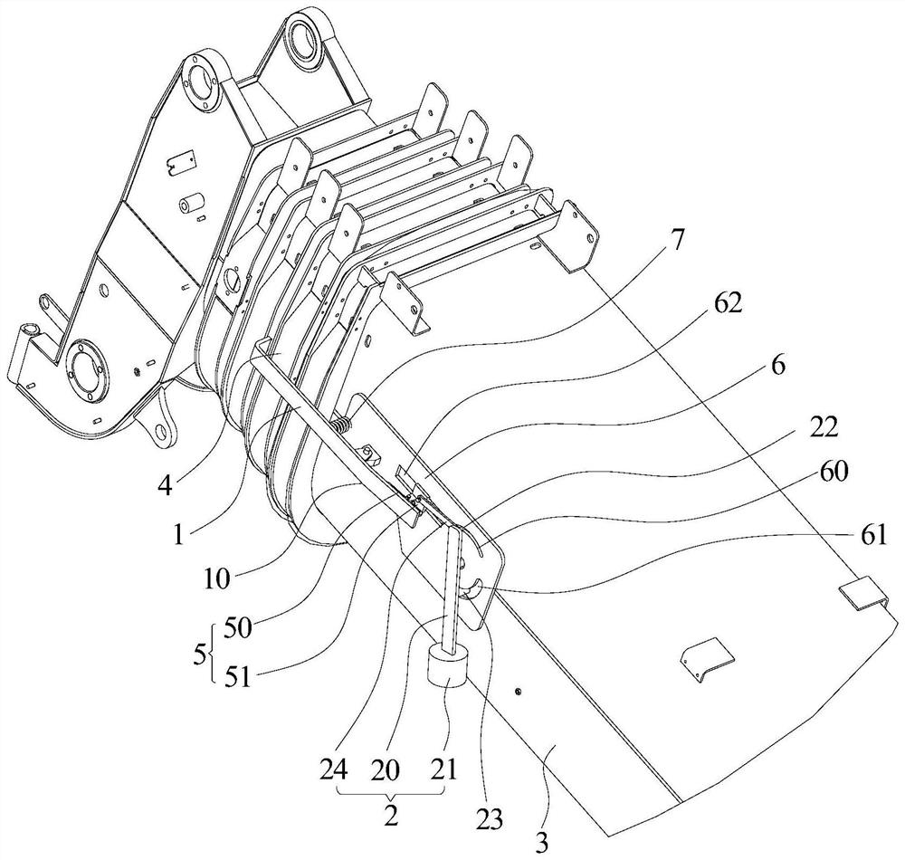
[0005] The purpose of the present invention is to provide a locking mechanism, a boom and a crane, so as to alleviate the separation structure between the power assembly and the working rod in the locking mechanism adopted on the boom of the truck crane existing in the prior art, Therefore, the transmission process between the power component and the working rod in the locking mechanism is not stable, and it is prone to disconnection, which leads to the technical problem that the locking mechanism cannot stably lock and unlock the jib.

Method used


Image

  • Locking Mechanisms, Booms and Cranes
  • Locking Mechanisms, Booms and Cranes
  • Locking Mechanisms, Booms and Cranes

Examples


Embodiment 1

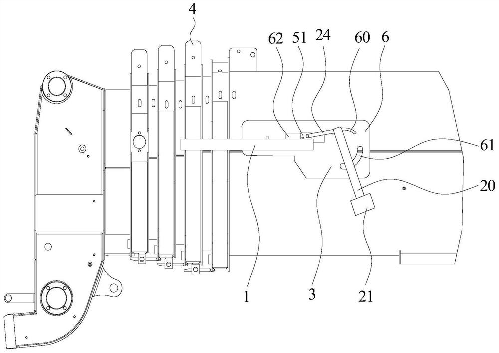
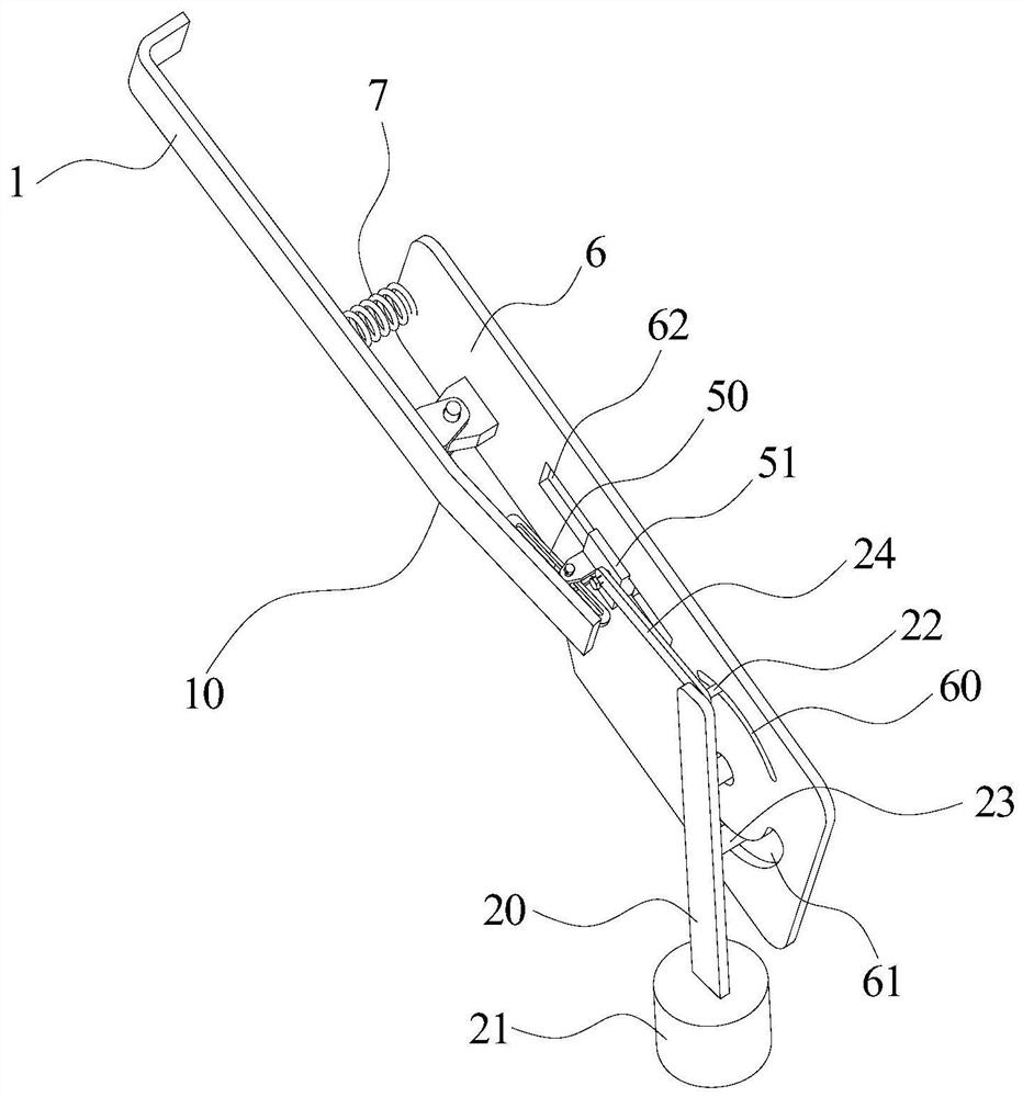
[0037] Such as Figure 1-Figure 3 As shown, the locking mechanism provided in this embodiment includes a locking lever 1 and a power assembly 2 . Such as figure 1 with figure 2 As shown, the position between the two ends of the locking rod 1 is hinged on the basic arm 3 of the boom, one end of the locking rod 1 is located on one side of the jib 4 of the boom, and the other end of the locking rod 1 is connected to the The output ends of the power components 2 are connected through a sliding pair 5 . Such as figure 1 with image 3 As shown, the sliding pair 5 and the power assembly 2 are installed on the basic arm 3 of the boom, and the power assembly 2 is used to drive the sliding pair 5 to slide in a direction inclined to the basic arm 3 of the boom to drive the locking lever 1 One end connected with the sliding pair 5 is close to or far away from the basic arm 3 of the boom. In this embodiment, the jib may be a jib on a truck crane. Further, the boom may include a bas...

Embodiment 2

[0086] The jib provided in this embodiment includes a basic arm, an auxiliary arm and the locking mechanism in the first embodiment. The auxiliary arm is slidingly connected with the basic arm, and the locking mechanism is installed between the basic arm and the auxiliary arm.

[0087] The boom provided in this embodiment includes the locking mechanism in Embodiment 1, so the boom provided in this embodiment and the locking mechanism in Embodiment 1 can solve the same technical problem and achieve the same technical effect.

[0088] The boom provided by this embodiment also alleviates the separation structure between the power assembly and the working rod in the locking mechanism adopted on the boom of the truck crane existing in the prior art, so the power assembly in the locking mechanism and the working rod are separated. The transmission process between the working rods is not stable, and it is prone to disconnection, which leads to the technical problem that the locking m...

Embodiment 3

[0090] The crane provided in this embodiment includes the boom in Embodiment 2, so the crane provided in this embodiment and the boom in Embodiment 1 can solve the same technical problem and achieve the same technical effect.

[0091] The crane provided by this embodiment also alleviates the separation structure between the power assembly and the working rod in the locking mechanism adopted on the boom of the truck crane existing in the prior art, so the power assembly and the working rod in the locking mechanism The transmission process between them is not stable, and it is prone to disconnection, which leads to the technical problem that the locking mechanism cannot stably lock the auxiliary arm and unlock the auxiliary arm.


PUM


Abstract

The invention provides a locking mechanism, a boom and a crane, and relates to the technical field of engineering machinery. The locking mechanism includes a locking lever and a power assembly; the position between the two ends of the locking lever is hinged on the basic arm of the boom, one end of the locking lever is located on one side of the jib of the boom, and the other end of the locking lever is One end is connected to the output end of the power assembly through a sliding pair; both the sliding pair and the power assembly are installed on the basic arm, and the power assembly is used to drive the sliding pair to slide in the direction inclined to the basic arm of the boom to drive the locking lever The end connected with the sliding pair is close to or away from the basic arm of the boom. The present invention alleviates the problem that the power assembly and the working rod in the locking mechanism on the boom of the truck crane in the prior art are separated structures, and the transmission process between the power assembly and the working rod is not stable, resulting in that the locking mechanism cannot Stable technical issues of locking the jib and unlocking the jib.

Description

technical field [0001] The invention relates to the technical field of engineering machinery, in particular to a locking mechanism, a lifting arm and a crane. Background technique [0002] When the truck crane stops and brakes suddenly during travel, due to inertia, the jib in the boom of the truck crane will move forward relative to the basic boom, which brings certain safety hazards to the braking of the crane. [0003] In order to prevent the auxiliary arm in the boom from moving forward relative to the basic arm during the braking process of the truck crane, a locking mechanism is installed between the basic arm and the auxiliary arm of the existing truck crane. Rod and power assembly, the middle part of the working rod is hinged on the basic arm, one end of the working rod is hook-shaped and is located on one side of the auxiliary arm, and the other end of the working rod is located on one side of the basic arm. The power assembly can be inserted between the basic arm ...

Claims


Application Information

Patent Timeline
Patent Type & Authority Patents(China)
IPC IPC(8): B66C23/70
CPCB66C23/708
Inventor 韩奎游浩杰喻露
Owner SANY AUTOMOBILE HOISTING MACHINERY
Learn More