Pneumatic-electric hybrid force control end effector for robot

An end effector and hybrid technology, which is applied in the direction of grinding machine parts, workpiece feed movement control, grinding frame, etc., can solve the problem of not meeting the requirements of real-time rapid force control and the small range of force adjustment , easy to produce vibration and other problems, to achieve the effect of large force-to-weight ratio, large force control adjustment range, and low production cost

Active Publication Date: 2020-10-09
NINGBO INST OF MATERIALS TECH & ENG CHINESE ACADEMY OF SCI
View PDF2 Cites 5 Cited by
  • Summary
  • Abstract
  • Description
  • Claims
  • Application Information

AI Technical Summary

Problems solved by technology

Due to the shortcomings of the pneumatic system itself, such as slow response, low precision, and long hysteresis time, it cannot well meet the real-time and rapid force control requirements during the polishing process.
The electric drive type realizes the force output of the end effector through the telescopic movement of the linear motor. The advantages are high force control precision and fast response speed, but this method has disadvantages such as poor flexibility and large quality, and it is easy to generate vibration during the polishing process.
The existing gas-electric hybrid makes up for the shortcomings of poor flexibility of the electric drive, but the mass is still relatively large, and the output force is too large, and the force adjustment range is small, which cannot meet the needs of actual working conditions.

Method used


Image

  • Pneumatic-electric hybrid force control end effector for robot
  • Pneumatic-electric hybrid force control end effector for robot
  • Pneumatic-electric hybrid force control end effector for robot

Examples


Embodiment Construction

[0028] The present invention will be further described in detail below in conjunction with the embodiments and the accompanying drawings. It should be noted that the following embodiments are intended to facilitate understanding of the present invention, but do not limit it in any way.

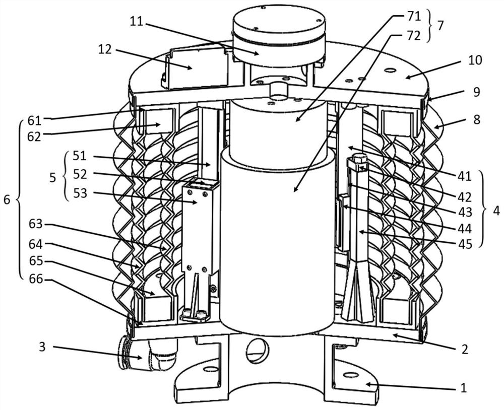
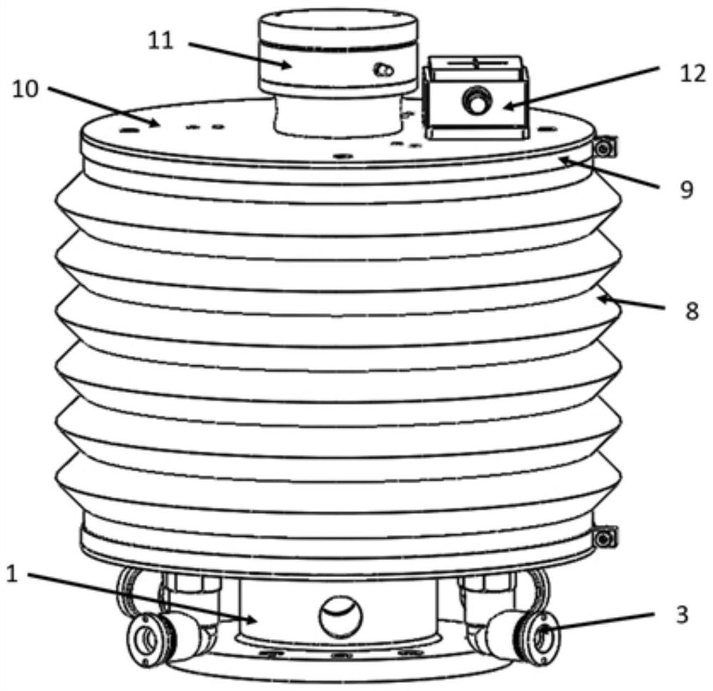
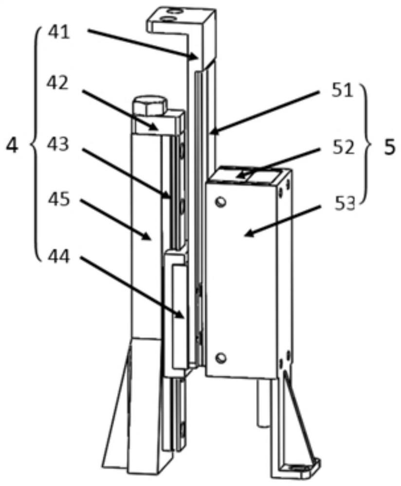
[0029] In this embodiment, the gas-electric hybrid force-controlled end effector includes a fixed platform 2 articulated with the end of the mechanical arm, and a movable platform 10 that can move relative to the fixed platform 2 through a guide device 4 . Between the moving platform 10 and the fixed platform 2, an air telescopic spring 6 and a linear motor arranged in parallel are arranged to drive the moving platform 10 to move axially along the guide device 4. The guide device 4 is provided with a displacement sensor 5 for detecting the moving position of the moving platform 10, the moving platform 10 is provided with a pressure sensor 11 and an inclination sensor 12, the displacement sensor...


PUM


Abstract

The invention discloses a pneumatic-electric hybrid force control end effector for a robot. The pneumatic-electric hybrid force control end effector comprises a fixed platform connected to an end joint of a mechanical arm, and a mobile platform that can move relative to the fixed platform through a guide device; an air telescopic spring and a linear motor arranged in parallel are arranged betweenthe mobile platform and the fixed platform and used for driving the mobile platform to move axially along the guide device; the guide device is provided with a displacement sensor used for detecting the moving position of the mobile platform; the mobile platform is provided with a pressure sensor and a tile angle sensor; the displacement sensor, the pressure sensor and the tile angle sensor send feedback signals to a controller; and the controller adjusts the output force of the air telescopic spring and the linear motor to realize the decoupling of the force / position control of the mechanicalarm. The pneumatic-electric hybrid force control end effector for the robot provided by the invention adopts the pneumatic-electric hybrid drive, has the advantages of being high in precision, fast in response, good in flexibility, large in force control adjustment range, light in weight, low in cost and the like, can realize surface finishing of a continuous curved surfaces, and is especially suitable for the polishing and grinding industry.

Description

technical field [0001] The invention relates to an end effector device in the field of industrial robots, in particular to a gas-electric hybrid force-controlled end effector for a robot. Background technique [0002] In the process of mechanical processing and mold production, there are often some problems on the surface of the processed workpiece, such as surface roughness, surface scratches and edge burrs, etc. These problems seriously affect the surface quality of the workpiece, which further leads to an increase in the reject rate of the product . In order to improve the surface quality of the workpiece and reduce the reject rate of the product, it is usually necessary to carry out surface finishing on the processed workpiece. [0003] With the development of science and technology, industrial robots are more widely used in mechanical production, not only for non-continuous contact operations, such as loading and unloading, welding, spraying, etc., but also for contact...

Claims


Application Information

Patent Timeline
Patent Type & Authority Applications(China)
IPC IPC(8): B24B41/00B24B41/02B24B41/04B24B49/04
CPCB24B41/00B24B41/02B24B41/04B24B49/04
Inventor 杨桂林刘立涛张林张驰朱任峰
Owner NINGBO INST OF MATERIALS TECH & ENG CHINESE ACADEMY OF SCI
Why Eureka
Try Eureka