
A Hybrid Excitation Switched Reluctance Motor with Modular Rotor

A technology of switched reluctance motor and mixed excitation, which is applied in the direction of magnetic circuits, electromechanical devices, electrical components, etc. It can solve the problems of limiting the output capacity of the motor, affecting the mechanical strength of the rotor, and reducing the reliability of the motor, so as to achieve high electromagnetic utilization. , reduce the equivalent air gap length, reduce the effect of iron loss

Active Publication Date: 2022-03-25
UNIV OF ELECTRONICS SCI & TECH OF CHINA
View PDF16 Cites 0 Cited by
  • Summary
  • Abstract
  • Description
  • Claims
  • Application Information

AI Technical Summary

Problems solved by technology

The position of the permanent magnet of the motor increases the equivalent air gap length, which not only increases the volume of the motor, but also weakens the magnetic density of the air gap, which limits the output capacity of the motor.
When the permanent magnet is installed on the rotor, there is a problem of heat dissipation, which leads to the risk of demagnetization and loss of magnetism of the permanent magnet, and the reliability of the motor is reduced.
Embedding permanent magnets in the rotor segment will affect the mechanical strength of the rotor

Method used


Image

  • A Hybrid Excitation Switched Reluctance Motor with Modular Rotor
  • A Hybrid Excitation Switched Reluctance Motor with Modular Rotor
  • A Hybrid Excitation Switched Reluctance Motor with Modular Rotor

Examples


Embodiment

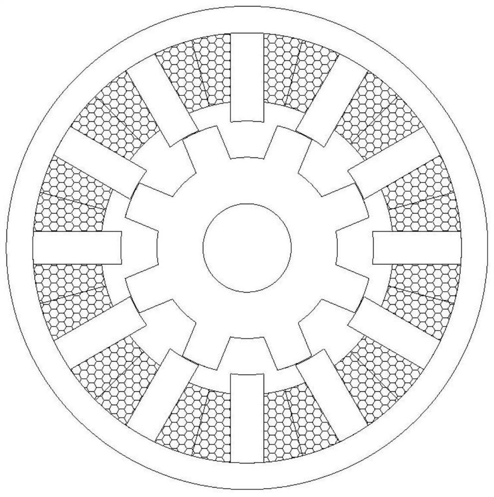
[0034] figure 1 It is a schematic diagram of a rotor modularized hybrid excitation switched reluctance motor of the present invention.

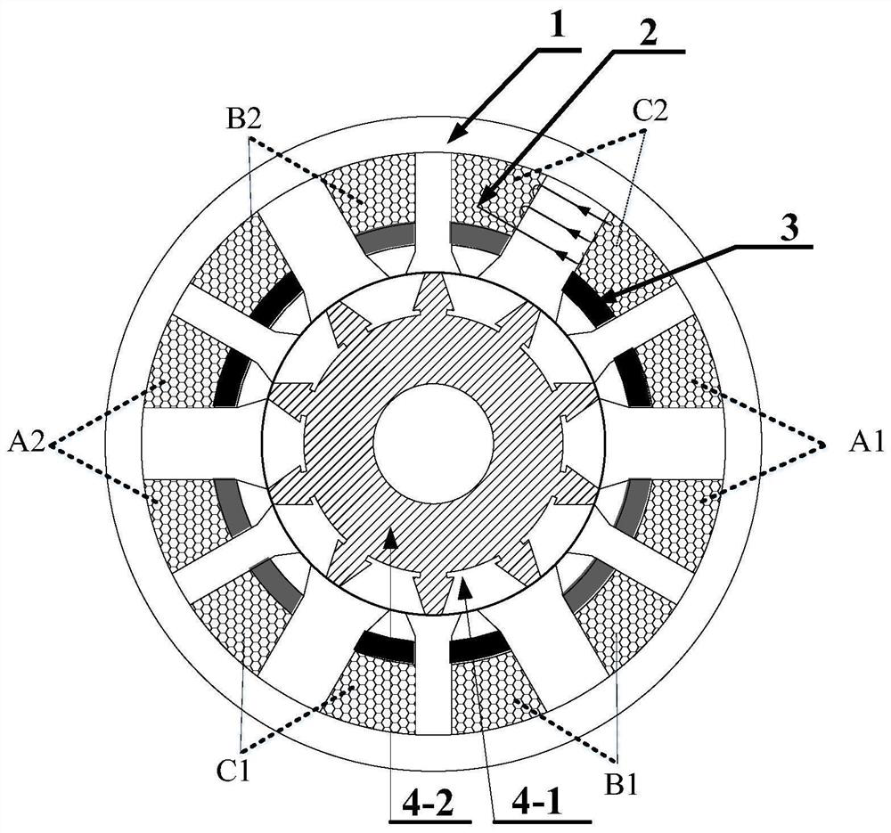
[0035] In this embodiment, as figure 2 As shown, the present invention is a rotor modular hybrid excitation switched reluctance motor, comprising: a stator core 1, an excitation winding coil 2, a permanent magnet 3, and a rotor 4;

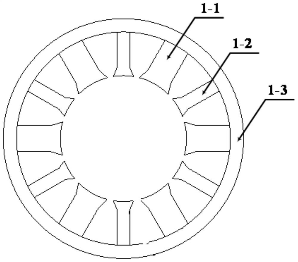
[0036] like image 3 As shown, the stator core 1 is a salient pole structure, including stator poles and stator yokes 1-3;

[0037] Among them, the stator yoke 1-3 is annular, and the stator poles are composed of six groups of excitation poles 1-1 and auxiliary poles 1-2 that are alternately and evenly distributed inside the stator yoke. The lower ends of the excitation poles and auxiliary poles are rectangular blocks, and the upper ends are It is an isosceles trapezoid block, but the upper bottom of the isosceles trapezoid block is an arc with the axis of the motor as the center of the circle; Figure 4 As s...


PUM


Abstract

The invention discloses a rotor modular hybrid excitation switched reluctance motor, which mainly includes a stator core, an excitation winding coil, a permanent magnet and a rotor; the working principle of the hybrid excitation switched reluctance motor also follows the "minimum reluctance principle"—— The magnetic flux always forms a closed loop along the path with the least reluctance. When the rotor core of the motor is close to the position of the least reluctance, the main central axis of the motor coincides with the axis of the magnetic field; by changing the stator excitation to a mixed excitation, the increase The air gap magnetic density is reduced, and the saturation of the iron core material in the stator pole part is reduced, thereby enhancing the torque output capability of the motor. The outer surface of the rotor is cylindrical, which reduces the wind friction loss when the motor runs at high speed and improves the energy efficiency of the motor.

Description

technical field [0001] The invention belongs to the technical field of switched reluctance motors, and more particularly relates to a hybrid excitation switched reluctance motor with a modular rotor. Background technique [0002] Switched reluctance motor is a mechatronics product that began to enter the application field in the 1980s, and is a new branch in the field of speed regulation. It has the characteristics of simple structure, low cost, flexible control and strong adaptability to harsh environments such as high temperature. Based on the above advantages, switched reluctance motors have application advantages in electric vehicle systems, aerospace, and new energy systems, and have become the main focus of research and development in various countries. The structure of the traditional switched reluctance motor is as follows figure 1 As shown, the stator and rotor cores are all salient pole structures, and the size of each stator pole is the same. The salient pole ro...

Claims


Application Information

Patent Timeline
Patent Type & Authority Patents(China)
IPC IPC(8): H02K1/14H02K1/17H02K1/22H02K3/28H02K3/18H02K3/12
CPCH02K1/146H02K1/17H02K1/22H02K3/28H02K3/18H02K3/12H02K2213/12
Inventor 张蔓胡维昊李坚黄琦谢鸿钦张真源杜月芳蔡东升井实曹迪
Owner UNIV OF ELECTRONICS SCI & TECH OF CHINA
Learn More