An optical correction method for reflective deimage rotation components of aerospace optical remote sensing instruments

A technology of optical remote sensing and optical correction, which is applied in optical components, instruments, optics, etc., can solve the problems of public reports on the optical correction of reflective anti-image rotation components of aerospace optical remote sensing instruments, etc., achieve fast and accurate correction, improve The effect of correcting precision

Active Publication Date: 2022-02-18
SHANGHAI INST OF TECHNICAL PHYSICS - CHINESE ACAD OF SCI
View PDF5 Cites 0 Cited by
  • Summary
  • Abstract
  • Description
  • Claims
  • Application Information

AI Technical Summary

Problems solved by technology

[0004] At present, there is no public report on the optical correction of the reflective anti-image rotation component of aerospace optical remote sensing instruments

Method used


Image

  • An optical correction method for reflective deimage rotation components of aerospace optical remote sensing instruments
  • An optical correction method for reflective deimage rotation components of aerospace optical remote sensing instruments
  • An optical correction method for reflective deimage rotation components of aerospace optical remote sensing instruments

Examples


Embodiment

[0027] The optical correction of the reflective anti-image rotation component of the DQ-1 satellite wide imaging spectrometer has been successfully completed by using the above method.

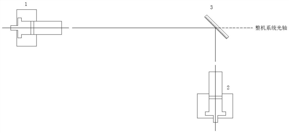
[0028] Such as figure 2 , adjust the central optical axis of the No. 1 internal focusing telescope 1 to coincide with the optical axis of the whole system, and pass the optical axis of the No. 2 internal focusing telescope 2 through the 45-degree turning plane mirror 3 and the No. 1 internal focusing telescope 1 The central optical axes of the telescopes coincide, that is, the central optical axes of the two inner focusing telescopes coincide and coincide with the optical axis of the whole machine system.

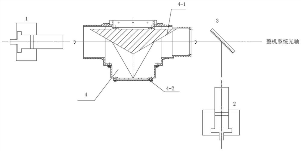
[0029] Paste the cross target paper on both ends of the hollow motor of the image elimination rotation assembly 4, so that the cross point on the target paper is the rotation center of the image elimination rotation assembly 4. Put the image elimination rotation assembly 4 into the optica...


PUM


Abstract

The invention discloses an optical correction method for a reflection-type anti-image rotation component of an aerospace optical remote sensing instrument. Two internal focusing telescopes that are coaxial with each other and coincide with the optical axis of the whole machine are used to align the rotating shafts at both ends of the anti-image rotation component respectively. The center can quickly adjust and coincide the rotation axis of the image elimination rotator assembly with the optical axis of the whole system, and accurately judge and correct the relative position between the internal optical reflection surfaces of the image elimination rotator assembly. Optical correction of the three-axis coincidence of the optical axis of the machine system. When the anti-image rotation assembly rotates, the included angle between the shaking of the image point around the axis and the optical axis of the whole system is better than 10". The advantage of the present invention is that the method of the present invention quickly and accurately corrects the reflective anti-image rotation assembly of the aerospace optical remote sensing instrument, By improving the coincidence accuracy of the optical axis of the inner focusing telescope, the optical axis of the whole machine system and the rotation axis of the image elimination rotation assembly, the correction accuracy of the image elimination rotation assembly can be improved.

Description

technical field [0001] The invention relates to an optical correction method for a reflective deimage rotation component of an aerospace optical remote sensing instrument. Background technique [0002] Many aerospace optical remote sensing instruments use a 45-degree rotating scanning mirror scanning method. In order to eliminate the reflection image rotation caused by the 45-degree scanning mirror rotation, it is necessary to use a reflective de-rotation component in the optical system. When the reflective de-rotation component is combined with The rotation direction of the 45-degree scanning mirror is consistent and the rotation speed is half of the 45-degree scanning mirror, which can eliminate the image rotation. [0003] The anti-image rotation assembly is composed of three reflective surfaces, and the two reflective surfaces form a V-shaped block with an integrated structure. The mechanical axis of the anti-image rotation assembly needs to coincide with the optical axi...

Claims


Application Information

Patent Timeline
Patent Type & Authority Patents(China)
IPC IPC(8): G02B27/62G02B7/182
CPCG02B27/62G02B7/1821
Inventor 张锷雷松涛马培龙
Owner SHANGHAI INST OF TECHNICAL PHYSICS - CHINESE ACAD OF SCI
Why Eureka
Try Eureka