
Electric control water pump control method and ECU

A technology of electronically controlled water pumps and control methods, which is applied in pump control, liquid variable displacement machinery, exhaust gas recirculation, etc., and can solve problems such as overheating of EGR coolers

Active Publication Date: 2020-10-02
WEICHAI POWER CO LTD
View PDF4 Cites 4 Cited by
  • Summary
  • Abstract
  • Description
  • Claims
  • Application Information

AI Technical Summary

Problems solved by technology

[0005] The object of the present invention is to provide an electronically controlled water pump control method and ECU to solve the local overheating problem inside the EGR cooler

Method used


Image

  • Electric control water pump control method and ECU
  • Electric control water pump control method and ECU
  • Electric control water pump control method and ECU

Examples


Embodiment Construction

[0040] By way of the above drawings, specific embodiments of the invention have been shown and will be described in more detail hereinafter. These drawings and written descriptions are not intended to limit the scope of the inventive concept in any way, but to illustrate the inventive concept for those skilled in the art by referring to specific embodiments.

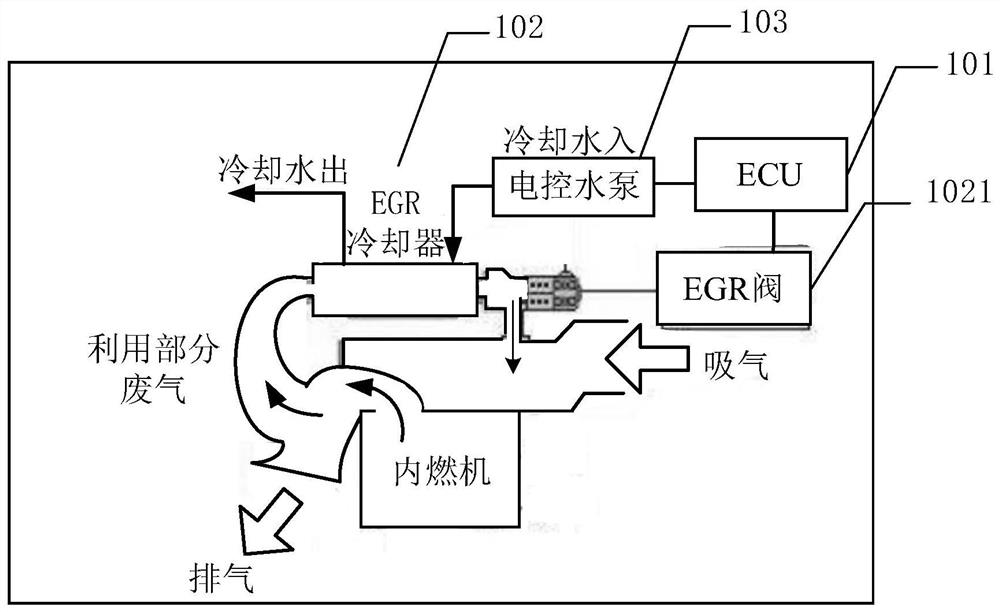
[0041] figure 1 The schematic structural diagram of the EGR system provided by the embodiment of the present invention, such as figure 1 As shown: the EGR system in the embodiment of the present invention includes: an electronic control unit (Electronic Control Unit, ECU) 101 , an EGR cooler 102 and an electronically controlled water pump 103 . Wherein the EGR cooler 102 further includes an EGR valve 1021 . The ECU 101 controls the rotational speed of the electronically controlled water pump 103 and the opening of the EGR valve 1021 , and the EGR cooler 102 cools the recovered exhaust gas through the cold water provide...


PUM


Abstract

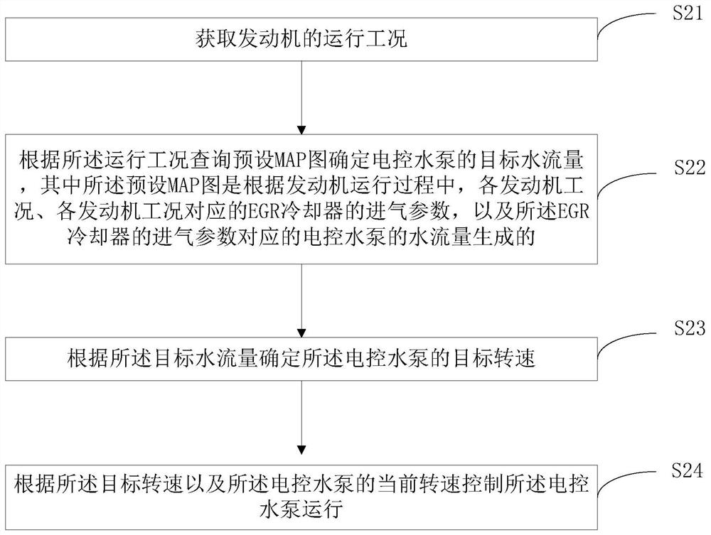
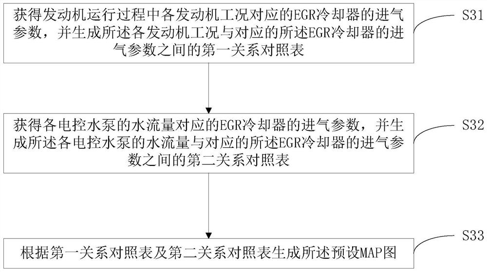
The invention provides an electric control water pump control method and an ECU. The method comprises the steps of obtaining the operating condition of an engine, inquiring a preset MAP according to the operating condition to determine the target water flow of an electric control water pump, determining the target rotating speed of the electric control water pump according to the target water flow, and controlling the electric control water pump to operate according to the target rotating speed and the current rotating speed of the electric control water pump. The minimum water flow corresponding to the operating condition of the engine is determined according to the preset MAP, the rotating speed of the electric control water pump corresponding to the minimum water flow is determined, andthe operation of the electric control water pump is controlled according to the target rotating speed and the current rotating speed of the electric control water pump, so that the problem of local overheating in an EGR cooler in a cooling process is avoided.

Description

technical field [0001] The invention relates to the technical field of engines, in particular to an electronically controlled water pump control method and an ECU. Background technique [0002] At present, engines generally use EGR (Exhaust Gas Recirculation, referred to as exhaust gas recirculation) system to reduce NOX emissions. By using the EGR cooler to cool a part of the exhaust gas discharged from the engine cylinder and mix it with fresh air before entering the engine, the exhaust gas reuse is realized. [0003] At present, the internal combustion engine industry generally detects the cooling effect of the EGR cooler by detecting the outlet temperature of the EGR cooler. When the outlet air temperature of the EGR cooler exceeds the set maximum temperature, the cooling water flow rate is increased by increasing the speed of the electronically controlled water pump to improve the cooling effect of the EGR cooler. [0004] However, by detecting the outlet air temperat...

Claims


Application Information

Patent Timeline
Patent Type & Authority Applications(China)
IPC IPC(8): F04B49/06F04B49/20F02M26/33
CPCF04B49/065F04B49/20F02M26/33
Inventor 么丽丽刘晓林尹召阳王洪忠张玉娟杨宇增
Owner WEICHAI POWER CO LTD
Learn More