
Electrical cabinet with insect-expelling and high-heat-dissipation functions

An electrical cabinet, high heat dissipation technology, applied in the direction of electrical components, electrical equipment structural parts, animal repellents, etc., can solve problems affecting electrical cabinets, equipment damage in power distribution cabinets, circuit short-circuits, etc., and achieve good cooling effect. Effect

Active Publication Date: 2020-09-29
重庆华美电力设备有限责任公司
View PDF7 Cites 7 Cited by
  • Summary
  • Abstract
  • Description
  • Claims
  • Application Information

AI Technical Summary

Problems solved by technology

[0003] Due to the diversity of industry settings such as power systems and fire safety monitoring, electrical cabinets sometimes need to be installed outdoors. Since the electronic components inside the electrical cabinet need to cooperate with flashing lights to control their operation, there are more light-loving mosquitoes outdoors. Accumulate in the electrical cabinet, and the mosquitoes will enter the electrical cabinet through the heat dissipation holes of the electrical cabinet, making the mosquitoes fly randomly in the electrical cabinet, which will easily cause damage to the equipment in the power distribution cabinet, and even lead to The short circuit of the circuit will cause fire and other dangers. Moreover, the accumulation of mosquitoes in the accessories of the electrical cabinet will affect the heat dissipation in the electrical cabinet, which will make the temperature of the electronic components in the electrical cabinet too high and reduce its service life.

Method used


Image

  • Electrical cabinet with insect-expelling and high-heat-dissipation functions
  • Electrical cabinet with insect-expelling and high-heat-dissipation functions
  • Electrical cabinet with insect-expelling and high-heat-dissipation functions

Examples


Embodiment Construction

[0022] In order to make the above objects, features and advantages of the present invention more comprehensible, specific implementations of the present invention will be described in detail below in conjunction with the accompanying drawings. In the following description, numerous specific details are set forth in order to provide a thorough understanding of the present invention. However, the present invention can be implemented in many other ways different from those described here, and those skilled in the art can make similar improvements without departing from the connotation of the present invention, so the present invention is not limited by the specific implementations disclosed below.

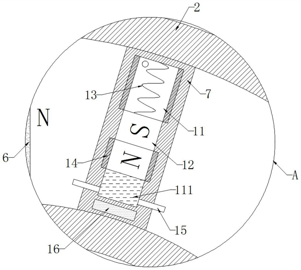
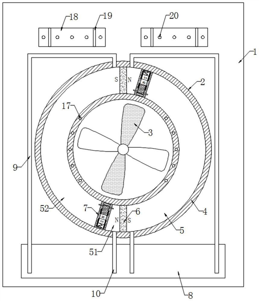
[0023] refer to Figure 1-5 , an electrical cabinet with insect repelling and high heat dissipation function, comprising a cabinet body 1, a through hole 2 is opened on the side wall of the cabinet body 1, and a plurality of impellers 3 are connected through the through hole 2 through...


PUM


Abstract

The invention discloses an electrical cabinet with insect expelling and high heat dissipation functions. The cabinet comprises a cabinet body, through holes are formed in the side wall of the cabinetbody; a plurality of impellers are rotationally connected into the through holes through rotating shafts; and circular rings are fixedly connected to the inner walls of the through holes, annular cavities are formed in the circular rings, two magnetic plates are symmetrically and fixedly connected to the positions over and under the inner wall of the annular cavity, the magnetism of the sides, close to each other, of the two magnetic plates is opposite, and two sliding plates are symmetrically and slidably connected to the inner walls of the annular cavities. According to the invention, the evaporated liquid is continuously heated and cooled; strip-shaped magnet slides up and down in a strip-shaped cavity; the magnetic poles of the strip-shaped magnets are replaced back and forth; the strip-shaped magnetic strips drive the sliding plates to periodically rotate clockwise and anticlockwise on the inner walls of the annular cavities under the action of magnetic force of the magnetic plates, cooling liquid in a heat absorption cavity and a heat exchange cavity circularly flows to be replaced, and the cooling liquid is kept at a low temperature all the time to absorb heat in the cabinetbody.

Description

technical field [0001] The invention relates to the technical field of electrical equipment, in particular to an electrical cabinet with insect repelling and high heat dissipation functions. Background technique [0002] The electrical cabinet is a commonly used electrical equipment. In order to meet the needs of some power systems and fire safety monitoring industries, it is necessary to configure the electrical cabinet to protect the electronic components required by these electrical equipment. [0003] Due to the diversity of industry settings such as power systems and fire safety monitoring, electrical cabinets sometimes need to be installed outdoors. Since the electronic components inside the electrical cabinet need to cooperate with flashing lights to control their operation, there are more light-loving mosquitoes outdoors. Accumulate in the electrical cabinet, and the mosquitoes will enter the electrical cabinet through the heat dissipation holes of the electrical cab...

Claims


Application Information

Patent Timeline
Patent Type & Authority Applications(China)
IPC IPC(8): H05K7/20A01M29/18
CPCH05K7/20309H05K7/20327H05K7/20136H05K7/20172A01M29/18
Inventor 卓烁民
Owner 重庆华美电力设备有限责任公司
Learn More