


Quick Research
Generate reliable direction feasibility study reports for your R&D in just a few steps.

Technical Q&A
Discover and master advanced knowledge NOW. Basics, ideas, possibilities, all at once.

Find Solutions
As an expert in R&D theories, this can generate solutions to your technical problems instantly.

Evaluate Feasibility
Analyze your overall solution with one click, know your potential R&D risks in advance.

Monitor Landscape
Get weekly tech updates, stay abreast of the latest tech innovations and key insights.
Intermediate-frequency ultrasonic signal processing application system received by energy converter
A signal processing and application system technology, applied in the field of ultrasound, can solve the problems of high AD chip, complex circuit, and limitation of ultrasonic signal sampling frequency, etc., and achieve the effect of reducing components, reducing design difficulty, reducing cost and application difficulty
- Summary
- Abstract
- Description
- Claims
- Application Information
AI Technical Summary
Problems solved by technology
Method used
Image

Examples
Embodiment 1
[0036] The invention adopts a dual-channel voltage feedback amplifier and a four-stage amplification filter sampling method of an RF power detector to realize the detection of ultrasonic reflection signals.
[0037] The present invention adopts a special amplifier, that is, a logarithmic detector, as a post-stage signal processing. The peripheral circuit of the special signal amplifier is simple, and the routing requirements of the signal line on the circuit board are not high, and the signal processed in the above four steps can be directly processed by frequency. The conversion between the domain and the time domain directly obtains the envelope of the effective signal, and the converted signal can be read and sampled by a general-performance ADC chip or an ADC module integrated on the MCU to obtain effective data.
[0038] An intermediate frequency ultrasonic signal processing application system received by a transducer according to the present invention includes:
[0039] ...
Embodiment 2
[0059] Embodiment is a modification of embodiment 1
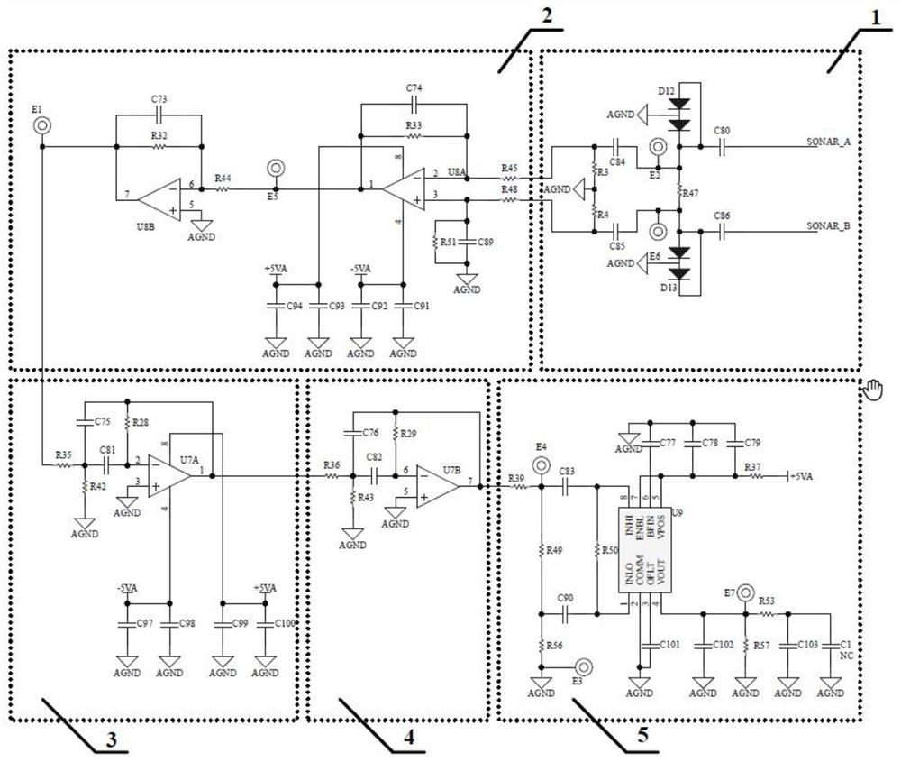
[0060] The ultrasonic reflection signals SONAR_A and SONAR_B in the signal sampling circuit are sampled by the filter capacitor and the half bridge, and the signal is loaded on both ends of the resistor R47 to form a differential signal, and the differential signal is input to the RC filter circuit again to obtain the differential signal into the first-level signal amplification circuit middle.
[0061] In the signal sampling circuit, the amplifier sampling dual power supply works
[0062]After the output signal is low-pass filtered by resistors R45 and R48 to remove burrs and noise signals, it is input to the second and third pins of the amplifier U8 to amplify the signal by 100 times and output it. The signal measurement point E5 can measure the amplified signal. The amplified signal is input to the sixth pin of the amplifier U8 to increase the output impedance of the signal. The output signal can be measured at the sign...
PUM
 Abstract
Description
Claims
Application Information
 - R&D Engineer
- R&D Manager
- IP Professional
- Industry Leading Data Capabilities
- Powerful AI technology
- Patent DNA Extraction
Browse by: Latest US Patents, China's latest patents, Technical Efficacy Thesaurus, Application Domain, Technology Topic, Popular Technical Reports.
© 2024 PatSnap. All rights reserved.Legal|Privacy policy|Modern Slavery Act Transparency Statement|Sitemap|About US| Contact US: help@patsnap.com