
A bank transaction workflow engine system

A workflow engine and workflow technology, applied in data processing applications, finance, instruments, etc., can solve problems such as inability to fully adapt to bank transaction systems, complex systems and functions, and poor code maintainability, and achieve easy design. and rearrangement, reducing the depth of coupling, and the effect of strong maintainability

Active Publication Date: 2022-06-28
江苏苏宁银行股份有限公司
View PDF3 Cites 0 Cited by
  • Summary
  • Abstract
  • Description
  • Claims
  • Application Information

AI Technical Summary

Problems solved by technology

At present, for most banks, the traditional transaction system is a combination of business logic and processing flow. Every business flow requires rigid judgment. The coupling between business logic and functional units is deep, and new business will be generated when the business process changes. In this way, the complexity of the system becomes higher and higher with the development of the business, and the maintainability of the code becomes worse and worse, which brings great risks and cost investment in development testing, operation and maintenance, which requires a set of Orchestrate business processes, separate business logic and process implementation, take banking and financial business needs as the leading factor, and flexibly design a workflow engine for processing various transaction scenarios
[0003] For the management of such process nodes and the connection control of processes, there are various types of workflow engine frameworks in the current market, such as jbpm workflow management system, SWF distributed scheduling framework, etc. These products often have complex systems and functions, and external dependencies There are many, and additional learning is required when integrating with the application system, and it cannot fully adapt to the bank transaction system. Therefore, a transaction workflow engine for complex scenarios in the bank is proposed.

Method used


Image

  • A bank transaction workflow engine system
  • A bank transaction workflow engine system
  • A bank transaction workflow engine system

Examples


Embodiment Construction

[0026] The present invention is further illustrated below in conjunction with the accompanying drawings and specific embodiments. The present embodiment is implemented on the premise of the technical solution of the present invention. It should be understood that these embodiments are only used to illustrate the present invention and not to limit the scope of the present invention.

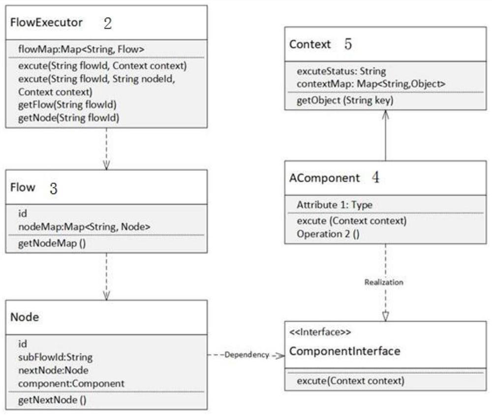
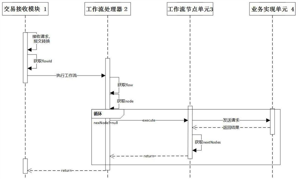
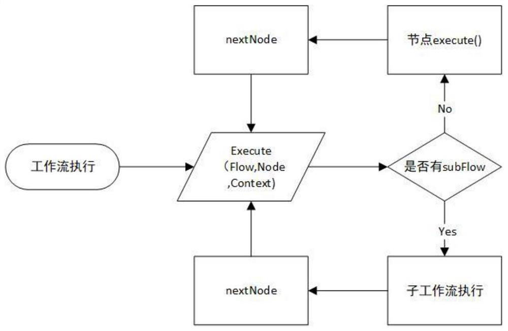
[0027] like figure 1 and 2 As shown, the embodiment of the present invention provides a bank transaction workflow engine system, including a transaction receiving unit 1, a workflow processor (FlowExecutor) 2, a workflow node unit 3, a business implementation unit (Component) 4 and a context unit ( Context)5.

[0028] Among them, the transaction receiving unit 1 is used to receive a user's transaction request, and convert the transaction request into an internal transaction object through a message, and the internal transaction object refers to the data in the internal format of the system.

[0...


PUM


Abstract

The invention discloses a bank transaction workflow engine system. The system includes a transaction receiving unit, a workflow processor, a workflow node unit, a business realization unit, a business realization unit and a context object unit. The present invention is realized based on java and configuration files, does not rely on any third-party framework, is simple, lightweight, and has strong scalability. The configuration files are mainly for the writing of business workflows, and the process management, process direction, and process processing of the engine are implemented in java, combined with java Adapter, factory, chain of responsibility and other modes are designed to fully meet the orchestration acceptance in different scenarios of complex business systems. It can also be strictly layered according to request reception, workflow processing, basic service implementation, and public component implementation to ensure a clear structure and clear layers, and the code is readable and maintainable. After receiving a transaction request, generally only need to perform basic processing such as conversion and verification on the request object, and then the workflow engine can be started.

Description

technical field [0001] The invention relates to the technical field of bank transaction systems, in particular to a bank transaction workflow engine system. Background technique [0002] With the rapid development of the financial industry, online and offline financial scenarios have become more abundant, user product experience has been continuously improved, and the functions of the bank's back-end transaction system have gradually increased. Inquiries have also added transaction scenarios such as credit lending, wealth management and cash withdrawal related to financial services, and the processing of various business transaction processes has become very cumbersome. At present, for most banks, the traditional transaction system is a combination of business logic and processing flow. Every business flow requires a rigid judgment. The business logic and functional units are deeply coupled, and new business will be generated when the business process changes. Logic, in thi...

Claims


Application Information

Patent Timeline
Patent Type & Authority Patents(China)
IPC IPC(8): G06Q10/10G06Q40/02
CPCG06Q10/103G06Q40/02
Inventor 金维东张磊邹建国
Owner 江苏苏宁银行股份有限公司
Learn More