


Quick Research
Generate reliable direction feasibility study reports for your R&D in just a few steps.

Technical Q&A
Discover and master advanced knowledge NOW. Basics, ideas, possibilities, all at once.

Find Solutions
As an expert in R&D theories, this can generate solutions to your technical problems instantly.

Evaluate Feasibility
Analyze your overall solution with one click, know your potential R&D risks in advance.

Monitor Landscape
Get weekly tech updates, stay abreast of the latest tech innovations and key insights.
Laser projection device
A laser projection and laser technology, applied in projection devices, optics, optical components, etc., to eliminate the phenomenon of "color block" color cast and improve the display quality.
- Summary
- Abstract
- Description
- Claims
- Application Information
AI Technical Summary
Problems solved by technology
Method used
Image

Examples
Embodiment 1
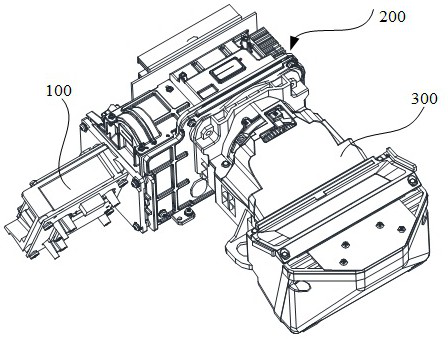
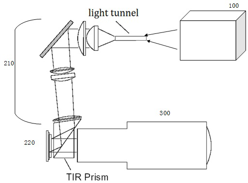
[0060] Embodiment 1 of the present application provides a laser projection device, Figure 5A-1 As shown, the laser projection device 10 includes a housing 101, and a projection imaging system wrapped in the housing 101. The projection imaging system includes a light source unit 100, an optical mechanical unit 200, and a lens unit 300, wherein the light source unit 100 emits three-color laser beams, and the three-color laser beams The polarization direction of the laser beam is different, such as Figure 6A As shown, the light source unit of the laser projection device in this example emits light in two polarization directions, P light and S light.
[0061] Figure 5A-2 for Figure 5A-1 A simplified schematic diagram of the decomposition. Such as Figure 5A-2 As shown, the laser projection device includes a light source unit 100. The three-color laser light emitted by the light source unit 100 is incident on the diffusion wheel 140. The rotation of the diffusion wheel diff...
Embodiment 2
[0091] Embodiment 2 provides a laser projection device, in which a moving phase retarder is arranged in the output light path of the light source unit. Specifically, such as Figure 8 As shown, the difference from the first embodiment is that the phase retarder is not arranged on the diffusion wheel 140, but can be arranged at multiple positions in the optical path.
[0092] In one implementation, such as Figure 8 As shown, the moving phase retarder can be arranged in the combined light output path of the light source unit 100 and at the P1 position before the incident diffusion wheel 140, preferably, the moving phase retarder is arranged between the beam shaping component and the diffusion wheel 140, The phase retarder can receive the reduced beam, and the size of the phase retarder itself can also be set smaller, which is beneficial to reduce the cost and the volume of the fixed structure and the driving structure. Moreover, realizing depolarization before the polychromat...
Embodiment 3
[0101] This implementation three provides a laser projection device, the application such as Figure 9A The light path shown.
[0102] Such as Figure 9A As shown, the light source part of the laser projection device includes at least three sets of laser assemblies, and each set of laser assemblies emits laser beams that are not used by the other two sets of laser assemblies.
[0103] The laser component 8110 emits light of a first color, the laser component 8102 emits light of a second color, and the laser component 8103 emits light of a third color.
[0104] The light of the three groups of laser components is combined through the combination lens group 8120, see Figure 9A , the light-combining lens group includes a fourth light-combining lens 8121 and a fifth light-combining lens 8122, wherein the first light-combining lens 8121 and the fifth light-combining lens 8122 may both be dichroic lenses.
[0105] Among them, the fourth light combining lens 8121 transmits the li...
PUM
 Abstract
Description
Claims
Application Information
 - R&D Engineer
- R&D Manager
- IP Professional
- Industry Leading Data Capabilities
- Powerful AI technology
- Patent DNA Extraction
Browse by: Latest US Patents, China's latest patents, Technical Efficacy Thesaurus, Application Domain, Technology Topic, Popular Technical Reports.
© 2024 PatSnap. All rights reserved.Legal|Privacy policy|Modern Slavery Act Transparency Statement|Sitemap|About US| Contact US: help@patsnap.com