Embedded fault injection module and method and high-speed digital circuit system

A fault injection, digital circuit technology, applied in the direction of digital circuit testing, radio wave measurement system, electronic circuit testing, etc., can solve the lack of reliable basis for the test design evaluation of high-speed digital circuit modules, can not solve the high-speed bus fault injection, difficult to implement Test verification methods, etc.

Active Publication Date: 2020-09-29
CHINA ELECTRONICS TECH GRP CORP NO 14 RES INST
View PDF7 Cites 1 Cited by
  • Summary
  • Abstract
  • Description
  • Claims
  • Application Information

AI Technical Summary

Problems solved by technology

[0003] 1. High-speed signals such as RapidIO and PCIE cannot perform fault injection, because high-speed serial bus signals such as RapidIO can only use point-to-point communication, it is difficult to intervene from the outside, and fault injection is difficult to achieve;
[0004] 2. High-speed signals such as RapidIO and PCIE cannot be verified for testability, because high-speed serial bus signals such as RapidIO are unfavorable faults, which makes testability verification impossible;
[0005] 3. High-speed digital circuit module testability design evaluation lacks reliable basis, fault injection is difficult to implement and testability verification methods are lacking, which makes testability design evaluation less reliable
[0006] 4. The software platform for testability verification of high-speed digital circuits is complex
The problem with this patent application is that the fault injection control system consists of a computer, a core control module, a standard interface, etc., involving complex host computer function software, etc.; the fault injection is the fault injection of various types of buses, which cannot solve the problems of RapidIO, PCIE, Difficulties of Fault Injection in High-Speed ​​Buses such as SERDES

Method used


Image

  • Embedded fault injection module and method and high-speed digital circuit system
  • Embedded fault injection module and method and high-speed digital circuit system
  • Embedded fault injection module and method and high-speed digital circuit system

Examples


Embodiment 1

[0041] An embodiment of the present invention introduces an embedded fault injection module and method, which are used for fault simulation and fault injection for radar high-speed digital circuit modules, and provide reliable basis for testing verification and evaluation of radar high-speed digital circuits.

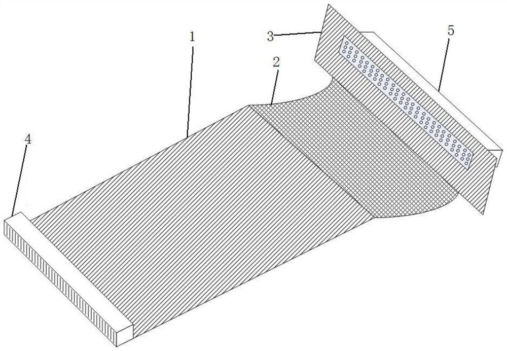
[0042] Such as figure 1 As shown, the embedded fault injection module of the high-speed digital circuit adopts a rigid-flexible PCB board, and the two ends of the PCB board are respectively provided with a first rigid PCB board 1 and a second rigid PCB board 3, and the first rigid PCB board 1 and the second rigid PCB board The middle of the rigid PCB 3 is provided with a flexible PCB 2 that is electrically connected to the first rigid PCB 1 and the second rigid PCB 3 . The free end of the first rigid PCB board 1 is provided with a first connector 4, which is used to connect the backplane of the radar digital circuit system working sub-box; one end of the second rigid PC...


PUM


Abstract

The invention belongs to the technical field of digital circuit testability verification, and discloses an embedded fault injection module, a high-speed digital circuit system and an embedded fault injection method. The embedded fault injection module comprises a signal path circuit which is used for ensuring that a high-speed digital circuit system has the same signal characteristics as before access after the embedded fault injection module is accessed and can intervene in a signal path during fault injection, a fault injection control circuit which is used for controlling the signal path circuit and controlling implementation of fault injection, a fault mode sub-module circuit that is used for storing a fault injection sequence according to a fault mode library of the high-speed digitalcircuit module and generating fault injection data of a low-speed signal, and a data communication circuit which is used for receiving and analyzing the fault mode simulation instruction of an uppercomputer and transmitting information to the fault injection control circuit. Therefore, a problem of high-speed signal fault injection of the high-speed digital circuit module can be solved.

Description

technical field [0001] The invention belongs to the technical field of radar testability verification, and in particular relates to an embedded fault injection module, a method and a high-speed digital circuit system. Background technique [0002] With the improvement of production and manufacturing technology, the integration of digital circuits is getting higher and higher. With the development of new technologies such as high-speed serial bus, the signal speed of digital circuits is getting higher and higher. It is becoming more and more difficult to simulate faults using traditional destructive physical means. Failure modes, fault injection and fault verification are more and more stuck in theoretical analysis. The coverage of injectable failure modes is decreasing, and failure modes such as high-speed signals cannot be actually injected. The reliability of product test design evaluation results is low, which cannot reflect the actual status of product test design, whic...

Claims


Application Information

Patent Timeline
Patent Type & Authority Applications(China)
IPC IPC(8): G01R31/317G01S7/40
CPCG01R31/31704G01S7/4004
Inventor 吕永乐曹子剑
Owner CHINA ELECTRONICS TECH GRP CORP NO 14 RES INST
Why Eureka
Try Eureka