
Intelligent well head safety control system with flow monitoring

A technology of safety control and flow monitoring, which is applied in wellbore/well components, wellbore/well valve devices, earthwork drilling and production, etc. It can solve problems such as safety valve leakage valve opening degree, leakage measurement monitoring, safety accidents, etc. To achieve the effect of improving safety production operation, reducing loss of production stoppage, and satisfying intelligence

Inactive Publication Date: 2020-09-29
维特力(深圳)流体工程有限公司
View PDF6 Cites 2 Cited by
  • Summary
  • Abstract
  • Description
  • Claims
  • Application Information

AI Technical Summary

Problems solved by technology

[0003] At present, the conventional wellhead control panel directly outputs hydraulic pressure to the downhole and uphole safety valves of the Christmas tree, and there is no leakage and flow detection of hydraulic oil between the wellhead control panel and the downhole and uphole safety valves of the Christmas tree, so as to judge the opening of the downhole and uphole safety valves of the Christmas tree Or shutting down is mainly judged by the pressure gauge of the wellhead control panel, but due to the poor working conditions of the valve in the downhole during actual use, it is easy to cause valve leakage accidents. At this time, the pressure gauge alone cannot realize hydraulic oil leakage and measurement monitoring. Secondly, , in the production operation, the opening and closing of the valve is not accurate only by the pressure judgment, and it is easy to cause safety accidents. Therefore, it is necessary to increase data such as flow measurement, combined with the opening curve of the downhole safety valve, and realize the comprehensive judgment of system leakage and valve opening through the host computer. , to solve the technical problems of safety valve leakage and valve opening degree, and realize the intelligent control of the wellhead control panel

Method used


Image

  • Intelligent well head safety control system with flow monitoring

Examples


Embodiment Construction

[0042] In order to further understand the content, features and effects of the present invention, the following embodiments are given as examples, and detailed descriptions are as follows with accompanying drawings:

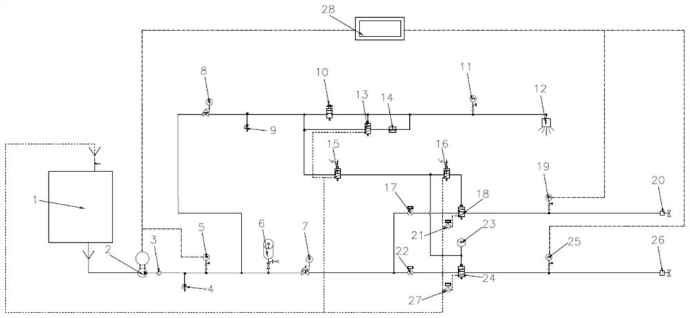
[0043] As attached figure 1 As shown, an intelligent wellhead safety control system with flow monitoring includes a high-pressure hydraulic system, a safety valve hydraulic control main road, a low-pressure control system, and a host computer control system 28.

[0044] The high-pressure hydraulic system includes: an oil tank 1, an electric hydraulic pump 2, a one-way valve 3, a first safety valve 4, a first pressure transmitter 5, an accumulator 6 and a first pressure regulating valve 7. The output end of the first pressure regulating valve 7 is respectively connected to the input end of the hydraulic control branch of the uphole safety valve and the hydraulic control branch of the downhole safety valve.

[0045] The safety valve hydraulic control main road includes a...


PUM


Abstract

The invention discloses an intelligent well head safety control system with flow monitoring. The intelligent well head safety control system with flow monitoring comprises a high-pressure hydraulic system, a safety valve hydraulic control main path, a low-pressure control system and an upper computer control system, wherein the safety valve hydraulic control main path comprises an overground safety valve hydraulic control branch and an underground safety valve hydraulic control branch, and the input ends of the two are connected to the output end of the high-pressure hydraulic system; the output end of the overground safety valve hydraulic control branch is connected to an overground safety valve, and the output end of the underground safety valve hydraulic control branch is connected to an underground safety valve; the low-pressure control system comprises a fusible plug control branch and a safety valve pilot control branch; the input end of the fusible plug control branch is connected to the output end of the high-pressure hydraulic system; and the fusible plug control branch is connected to the overground safety valve hydraulic control branch and the underground safety valve hydraulic control branch through the safety valve pilot control branch. The intelligent well head safety control system with flow monitoring solves the technical problem of safety valve leakage and valve opening degree judgment, and realizes intelligent control on a well head control disc.

Description

Technical field [0001] The invention relates to a wellhead safety control system, in particular to an intelligent wellhead safety control system with flow monitoring. Background technique [0002] The wellhead control panel is an important equipment for safe production in the oilfield. When the wellsite fires or the production pipeline pressure is abnormal, the control system can automatically realize the logic program emergency shutdown and remote emergency shutdown. The wellhead control panel can be used to relieve the pressure of the Christmas tree. And the safety valve on the well is turned off. [0003] At present, the conventional wellhead control panel directly outputs hydraulic pressure to the Christmas tree downhole and uphole safety valves, and there is no hydraulic oil leakage and flow detection between the wellhead control panel and the Christmas tree downhole and uphole safety valves to determine the opening of the Christmas tree downhole and uphole safety valves. Or ...

Claims


Application Information

Patent Timeline
Patent Type & Authority Applications(China)
IPC IPC(8): E21B34/02E21B34/10
CPCE21B34/02E21B34/10E21B34/108
Inventor 董明明彭起栋
Owner 维特力(深圳)流体工程有限公司
Learn More