Welding seam welding device used by being based on wind energy motor unit protection shell

A technology for protecting shells and welding devices, which is applied to auxiliary devices, welding equipment, auxiliary welding equipment, etc., and can solve problems such as difficult welding and poor quality

Pending Publication Date: 2020-09-29
李晶
View PDF6 Cites 2 Cited by
  • Summary
  • Abstract
  • Description
  • Claims
  • Application Information

AI Technical Summary

Problems solved by technology

[0003] The purpose of the present invention is to solve the defects of high welding difficulty and poor quality in the prior art, and propose a welding seam welding device based on the protective shell of wind energy generator sets

Method used


Image

  • Welding seam welding device used by being based on wind energy motor unit protection shell
  • Welding seam welding device used by being based on wind energy motor unit protection shell
  • Welding seam welding device used by being based on wind energy motor unit protection shell

Examples


Embodiment 1

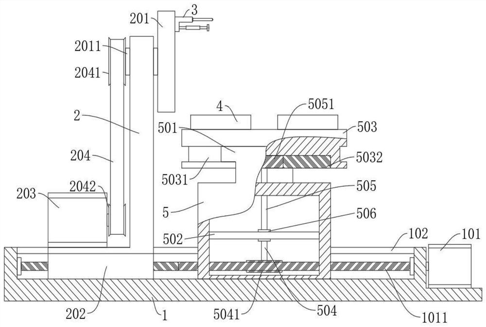
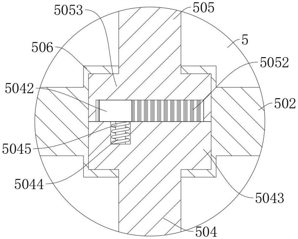
[0029] refer to figure 1 , image 3 and Figure 4, a seam welding device based on the protective shell of a wind energy generator, comprising a welding head 304, a three-jaw chuck 4, a base 1, a bracket 2 and a mounting seat 5 slidingly connected to the base 1, the bracket 2 and the mounting base 5 are fixedly connected with a first slider 202, the base 1 is provided with a first chute 102, the first slider 202 is slidably connected in the first chute 102, and the base 1 is fixedly connected with a first motor 101 , the output end of the first motor 101 extends to the first chute 102 and is fixedly connected with the worm 1011, the first slider 202 is provided with a worm thread hole matching the worm 1011, and the mounting seat 5 is rotatably connected with the first rotating shaft 504 and the second rotating shaft 505, one end of the first rotating shaft 504 is fixedly connected with the worm gear 5041 meshed with the worm 1011, the other end of the first rotating shaft 50...

Embodiment 2

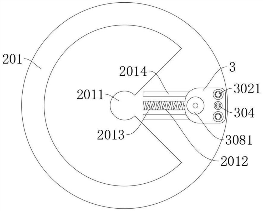
[0032] refer to Figure 3-5 , is basically the same as that of Embodiment 1, furthermore, the adjustment mechanism includes a first screw rod 307 and a second screw rod 308, the first screw rod 307 is screwed with the second screw rod 308 through a threaded sleeve 3072, and the first screw rod 307 is fixedly connected with a third sliding block 3071, the working head 3 is provided with a third chute 306, the third sliding block 3071 is slidably connected in the third chute 306, and the end of the second screw rod 308 away from the threaded sleeve 3072 is rotatably connected There is a roller 3081, the working head 3 is fixedly connected with a second slider 3011, the second slider 3011 is slidably connected in the second chute 2012, the first spring 2013 is offset against the second slider 3011, and the working head 3 is fixedly connected with a Auxiliary slider 3012, drive disc 201 is provided with auxiliary chute 2014, auxiliary slider 3012 is slidably connected in the auxil...

Embodiment 3

[0036] refer to figure 1 , is basically the same as Embodiment 1, furthermore, the driving part includes a second motor 203, the second motor 203 is fixedly connected on the support 2, the output end of the second motor 203 is fixedly connected with a second pulley 2042, and the drive shaft 2011 is fixedly connected with a first pulley 2041 at one end away from the drive disc 201, and the first pulley 2041 and the second pulley 2042 are connected in rotation through the belt 204. Here, when the second motor 203 drives the drive disc 201 to rotate through the belt 204 , the belt 204 can preferably choose a gear belt with a precise transmission ratio, so as to ensure the stable movement of the welding head 304 .


PUM


Abstract

The invention discloses a welding seam welding device used by being based on a wind energy motor unit protection shell, and belongs to the technical field of wind-driven generator shell welding. The welding seam welding device used by being based on the wind energy motor unit protection shell comprises a welding joint, a three-claw chuck, a base, a support and a mounting seat, wherein the supportand the mounting seat are in sliding connection to the base. A worm wheel engaged with a worm is connected to a first rotating shaft. Cooperating clamping mechanisms are arranged on the first rotatingshaft and a second rotating shaft. A first gear is connected to the second rotating shaft. A rotating table is rotationally connected to the top of the mounting seat, and a second gear is arranged inthe rotating table. A work head is in sliding connection to a drive disc, a first spring abuts against the work head, telescopic rods are in sliding connection in the work head, a ball is connected to each telescopic rod, the welding joint is in sliding connection in the work head, an adjusting plate is arranged between the telescopic rods and the welding joint, and an adjusting mechanism is in sliding connection in the work head. According to the welding seam welding device, the welding path is simulated through the work head, the welding distance is controlled through the adjusting plate, and it is guaranteed that the quality of welding seams is identical.

Description

technical field [0001] The invention relates to the technical field of wind energy generator shell welding, in particular to a weld seam welding device based on the protective shell of a wind energy generator set. Background technique [0002] The traditional welding methods are mostly operated by humans, and the welding in some complex environments will be replaced by robots, but the cost of robots is high, and they cannot be widely used. The head of the wind generator casing is a cylindrical structure , the outside needs to weld the cylindrical positioning sleeve for assembling the blades. Since its welding shape is elliptical in space and the shell volume is large, most of them require multiple groups of people to perform surrounding welding. The welding quality is uneven, and during the welding process It is necessary to grasp the welding depth according to the welding path in real time. The welding technology requires high requirements and the welding workload is large,...

Claims


Application Information

Patent Timeline
Patent Type & Authority Applications(China)
IPC IPC(8): B23K37/02B23K37/04
CPCB23K37/02B23K37/04B23K37/0443
Inventor 不公告发明人
Owner 李晶
Why Eureka
Try Eureka