A contact finger structure, an electrical connection structure, a channel selector and a power distributor
A technology of electrical connection structure and channel selection, applied in the direction of connection, components and circuits of connection devices, can solve the problems of damage to electric energy, large friction and loss of copper bars, prevent extrusion deformation, and realize high-power charging. Effect
- Summary
- Abstract
- Description
- Claims
- Application Information
AI Technical Summary
Problems solved by technology
Method used
Image
Examples
Embodiment 1
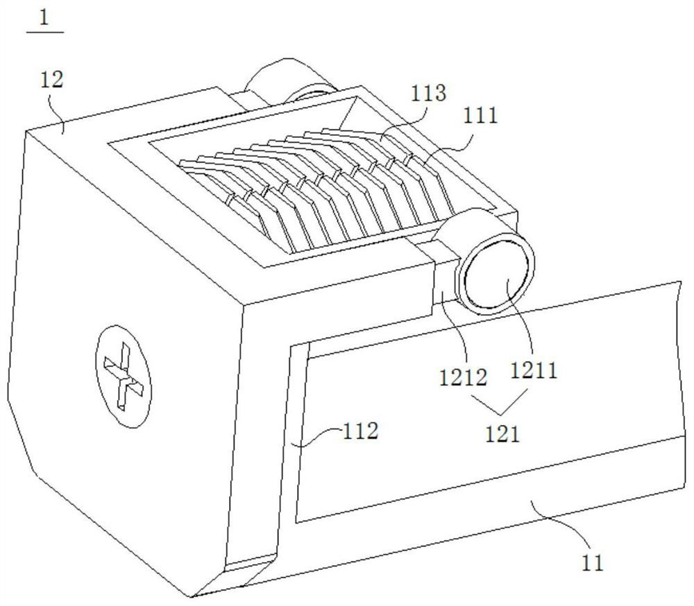
[0063] like figure 1 As shown, the contact finger structure 1 of this embodiment includes a conductor 11 and a carrier 12. The conductor 11 is provided with a contact portion 111 for overlapping with the contact copper bar, and a support arm extends on the carrier 12. The support arm A buffer portion 121 is connected. The buffer portion 121 includes an elastic cantilever 1212 and a buffer member 1211. One end of the elastic cantilever 1212 is connected to the support arm of the carrier 12, and the other end of the elastic cantilever 1212 is connected to the buffer member 1211. A part of the buffer member 1211 protrudes For the contact portion 111, when the contact portion 111 and the contact copper bar are overlapped, the protruding portion of the buffer member 1211 comes into contact with the contact copper bar before the contact portion 111. The buffer portion 121 in this embodiment is made of nylon plastic, which has high mechanical strength. , good toughness, not easy to b...
Embodiment 2
[0067] Another aspect of the present invention provides an electrical connection structure, such as figure 2 As shown, the electrical connection structure of this embodiment includes the finger structure 1 of the first embodiment and a contact pressure monitoring module. The contact pressure monitoring module includes a pressure sensing module 13, a control module and a driving module, and the pressure sensing module 13 is arranged in the buffer On the side of the part 121, the buffer part 121 is pressed to the pressure sensing module 13 when buffering, the pressure sensing module 13 sends a feedback signal to the control module, the control module controls the drive module to start and stop according to the feedback signal, and the drive module is used to drive the contact part 111. To carry out the lap joint action, specifically, the supporting body 12 in this embodiment also extends a supporting arm 131, and the supporting arm 131 is provided with a pressure sensing module ...
Embodiment 3
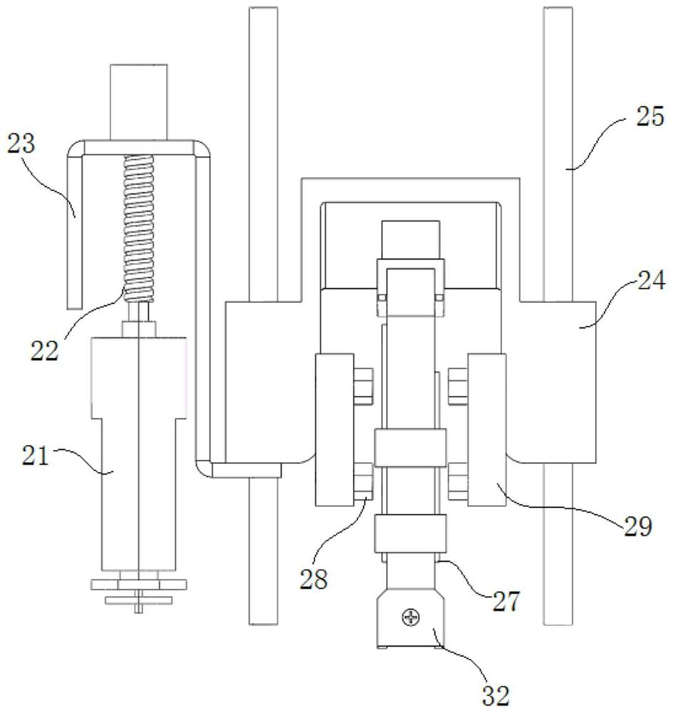
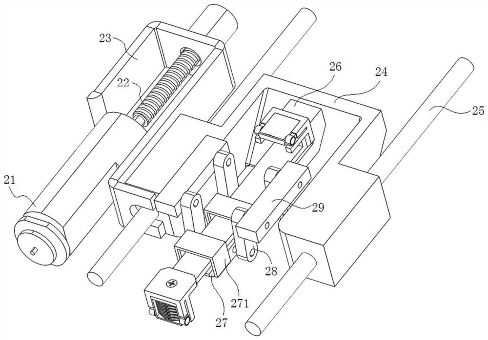
[0073] Another aspect of the present invention provides a channel selector, such as Figure 5-6 As shown, the channel selector 3 of the present embodiment includes the electrical connection structure of the second embodiment and the moving carrier 31. In the present embodiment, both ends of the conductive member 32 are provided with the contact finger structure 1 of the first embodiment. The finger structures 1 are respectively used to overlap with the horizontal copper bar 41 and the vertical copper bar 42. The moving carrier 31 is provided with an escape port 311 for the contact finger structure 1 at the first end and the second end of the conductive member 32 to overlap. The number of the components 32 is two, and the mobile carrier 31 in this embodiment is correspondingly provided with two sliding blocks 24 , a mobile base 26 and a deflection component respectively.
[0074] Further, the mobile carrier 31 also includes a casing 312 and a cover plate 313 , the fixing block ...
PUM
 Abstract
Description
Claims
Application Information
 - R&D Engineer
- R&D Manager
- IP Professional
- Industry Leading Data Capabilities
- Powerful AI technology
- Patent DNA Extraction
Browse by: Latest US Patents, China's latest patents, Technical Efficacy Thesaurus, Application Domain, Technology Topic, Popular Technical Reports.
© 2024 PatSnap. All rights reserved.Legal|Privacy policy|Modern Slavery Act Transparency Statement|Sitemap|About US| Contact US: help@patsnap.com


