Flexible assembling equipment for bridge T-shaped steel and implementation method thereof

A technology for assembling equipment and bridges, which is applied in the direction of bridge construction, bridge erection/assembly bridges, etc., can solve the problems of slow installation speed of bridge T-steel, large physical strength loss of operators, and slow assembly speed, etc., to achieve easy promotion and physical strength The effect of low consumption and fast assembly speed

Active Publication Date: 2020-09-25
江苏致信桥梁检测与维修加固有限公司
View PDF7 Cites 0 Cited by
  • Summary
  • Abstract
  • Description
  • Claims
  • Application Information

AI Technical Summary

Problems solved by technology

[0003] Today’s bridge T-steel needs to be installed in multiple pieces when it is used. Direct installation requires two bridge T-steel facing each other, and then the reinforcement plate and screws are fixed. The operation is very troublesome, and the assembly speed is slow, making the bridge T-steel The speed of steel installation is slowed down, and the physical strength of the operator is exhausted. In order to solve the above problems, a flexible assembly equipment for bridge T steel and its implementation method are proposed.

Method used


Image

  • Flexible assembling equipment for bridge T-shaped steel and implementation method thereof
  • Flexible assembling equipment for bridge T-shaped steel and implementation method thereof
  • Flexible assembling equipment for bridge T-shaped steel and implementation method thereof

Examples


Embodiment Construction

[0034] The technical solutions in the embodiments of the present invention will be clearly and completely described below in conjunction with the accompanying drawings in the embodiments of the present invention. Obviously, the described embodiments are only a part of the embodiments of the present invention, rather than all the embodiments. Based on the embodiments of the present invention, all other embodiments obtained by those of ordinary skill in the art without creative work shall fall within the protection scope of the present invention.

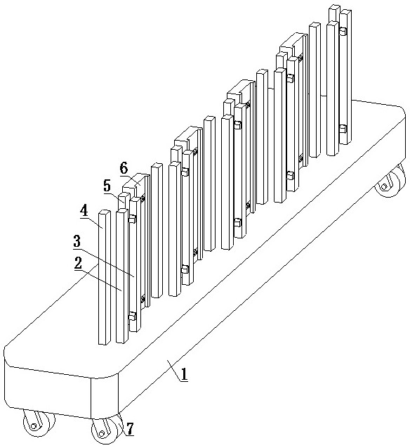
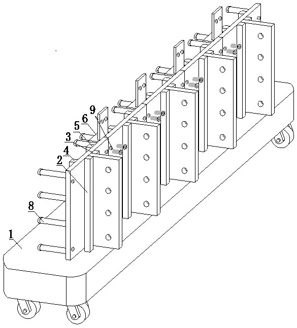
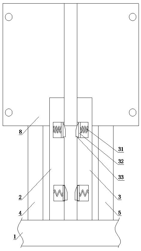
[0035] See Figure 1-2 And 9, a flexible assembly equipment for bridge T steel, comprising a support plate 1, a first clamping rod 2, a second clamping rod 3, a first blocking rod 4, a second blocking rod 5 and a clamping member 6, and The self-locking universal wheel 7 is included. The self-locking universal wheel 7 is installed at the lower end of the support plate 1, and is located at the four corners of the support plate 1 to facilita...


PUM


Abstract

The invention discloses flexible assembling equipment for bridge T-shaped steel and an implementation method thereof. The equipment comprises self-locking universal wheels mounted at the lower end ofa supporting plate; first clamping rods and second clamping rods are oppositely matched mechanisms; the first clamping rods and the second clamping rods are respectively arranged at the upper end of the supporting plate; one side of each first clamping rod and one side of each second clamping rod are arranged at the upper end of the supporting plate; T-shaped included angles of T-shaped steel areclamped among the first clamping rods, the second clamping rods, first stop rods and second stop rods; clamping pieces are arranged at the upper end of the supporting plate between the second stop rods and the first stop rods which are adjacent in different groups; reinforcing block assemblies are clamped between the clamping pieces and the adjacent T-shaped steel. The assembling equipment is simple in structure arrangement, low in manufacturing cost, capable of being produced in batches, convenient to popularize, convenient to move, small in occupied space, convenient to transport, high inassembling speed and low in physical output of operators; 2-5 pieces of T-shaped steel can be flexibly assembled according to requirements; and multiple pieces of assembling equipment can be arrangedwhen the required assembling amount is large.

Description

Technical field [0001] The invention relates to the technical field of bridge construction equipment, in particular to a flexible assembly equipment for bridge T steel and an implementation method thereof. Background technique [0002] Railway or highway bridges bear the impact load of vehicles. Bridge steel requires certain strength, toughness and good fatigue resistance, and requires high surface quality of the steel. The bridge steel often uses alkaline open-hearth killed steel, and has successfully used ordinary low-alloy steels such as 16 manganese, 15 manganese alumina nitrogen, etc. (YB168-70). The bridge steel should also have good welding performance and low notch sensitivity. , Bridge steel plate is a steel plate specially used to build railway or highway bridges. It is required to have high strength, toughness, and bear the load and impact of rolling stock, and have good fatigue resistance, certain low temperature toughness and atmospheric corrosion resistance. The T-...

Claims


Application Information

Patent Timeline
Patent Type & Authority Applications(China)
IPC IPC(8): E01D21/00
CPCE01D21/00
Inventor 丁西焘
Owner 江苏致信桥梁检测与维修加固有限公司
Why Eureka
Try Eureka