
Indoor sharing self-service vision detection system and detection method thereof

A vision detection and detection method technology, which is applied to eye testing equipment, character and pattern recognition, diagnosis, etc., can solve problems such as difficult query, inconformity with daily vision detection methods, and low recognition accuracy, so as to achieve permanent preservation and Query at any time, solve the problem of easy loss and difficult query, and improve user experience

Active Publication Date: 2020-09-25
福建生物工程职业技术学院
View PDF8 Cites 5 Cited by
  • Summary
  • Abstract
  • Description
  • Claims
  • Application Information

AI Technical Summary

Problems solved by technology

[0007] (1) Vision testing services usually need to go to ophthalmology institutions, optical shops and other places. For children and adolescents whose vision is changing rapidly, the current vision testing services are difficult to meet regular regular testing;
[0008] (2) Traditional detection methods or electronic vision detectors lack human-computer interaction, and the detection needs to be completed with the assistance of medical staff, and there is no way to achieve self-service detection
[0009] (3) The problem of vision data storage. Most of the current existing technologies are only responsible for measuring vision. The problem of vision data storage has not been well solved, resulting in data that is easy to lose, difficult to query, and unable to form a personal vision file;
[0010] (4) Use the method of image detection to carry out vision detection. Most of the methods are to judge the gestures in the vision detection through static gesture recognition, which does not conform to the daily vision detection method. The influence of light changes, resulting in low recognition accuracy

Method used


Image

  • Indoor sharing self-service vision detection system and detection method thereof
  • Indoor sharing self-service vision detection system and detection method thereof
  • Indoor sharing self-service vision detection system and detection method thereof

Examples


Embodiment Construction

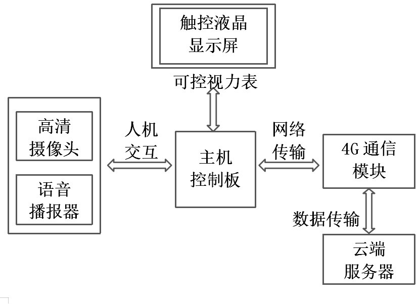
[0045] The present invention will be further described below in conjunction with the accompanying drawings and embodiments.

[0046] It should be pointed out that the following detailed description is exemplary and intended to provide further explanation to the present application. Unless defined otherwise, all technical and scientific terms used herein have the same meaning as commonly understood by one of ordinary skill in the art to which this application belongs.

[0047] It should be noted that the terminology used here is only for describing specific implementations, and is not intended to limit the exemplary implementations according to the present application. As used herein, unless the context clearly dictates otherwise, the singular is intended to include the plural, and it should also be understood that when the terms "comprising" and / or "comprising" are used in this specification, they mean There are features, steps, operations, means, components and / or combinatio...


PUM


Abstract

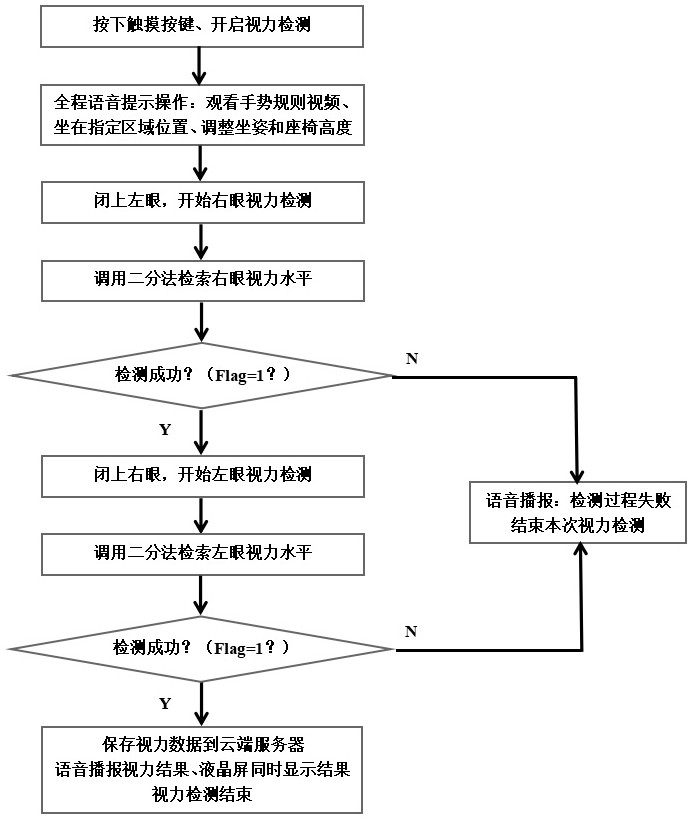
The invention relates to an indoor sharing self-service vision detection system and a detection method thereof. Vision detection is started, and a tester operates according to voice prompts of a voicebroadcaster. The vision of the right eye is detected firstly, the vision level of the right eye is retrieved by adopting a bisection method, and the specific process is as follows: when the tester sees a sighting mark of a display screen, gesture movement information is generated, a host calls a gesture movement detection algorithm based on a frame difference method to carry out single gesture information acquisition and direction discrimination, then whether the tester can see the sighting mark of the level clearly or not is judged according to a single-level sighting mark recognition and judgment rule, and the bisection method is circularly called to generate the sighting mark of the next level until it is detected that a tested person can see the sighting mark of the minimum level clearly. The process is repeated to complete a left eye vision test. A vision detection result can be stored in a cloud server terminal for the tester to call and check at any time. The vision detection process is convenient and fast, the detection efficiency is high, and self-service vision detection and regional sharing detection can be achieved.

Description

technical field [0001] The invention relates to the technical field of vision detection, in particular to an indoor shared self-service vision detection system and a detection method thereof. Background technique [0002] The traditional way of visual acuity testing is what we can often see in our daily activities. Under the guidance of a doctor and the instruction of the indicator rod, the subjects of the test will distinguish the visual targets on the eye chart in turn, and finally use the value of the visual targets to determine One of the most important characteristics of measuring the visual acuity level of the subject is that the doctor needs to control the whole process of the test. [0003] That is, a tester, a physician, an indicator rod, and an eye chart. Under the guidance of the physician, the tester distinguishes and points out the direction of the visual mark on the eye chart indicated by the indicator rod. However, due to the influence of many factors, such ...

Claims


Application Information

Patent Timeline
Patent Type & Authority Applications(China)
IPC IPC(8): A61B3/032A61B3/00G16H40/63G06K9/00G06F3/0488G06K17/00
CPCA61B3/032A61B3/0041G16H40/63G06F3/0488G06K17/0029G06V40/28Y02D30/70
Inventor 李昌锋曾燕茹林蔚童文琴张星
Owner 福建生物工程职业技术学院
Learn More