
Control rod driving mechanism state monitoring and health management method and system

A driving mechanism, monitoring and management technology, applied in nuclear reactor monitoring, reactors, nuclear power generation, etc., can solve the problem of equipment manufacturers and nuclear power plants lacking control rod driving mechanism mechanical equipment continuity, intelligent state monitoring, and interference with safe operation of reactors , motion structure deformation and other issues

Pending Publication Date: 2020-09-22
上海核工程研究设计院股份有限公司
View PDF0 Cites 3 Cited by
  • Summary
  • Abstract
  • Description
  • Claims
  • Application Information

AI Technical Summary

Problems solved by technology

[0003] First, the claw part is the core action mechanism of the control rod drive mechanism. The three sets of magnetic pole armature pairs drive the connecting rod, pin shaft, and claw to transmit the movement. The main failure mode is that the transmission structure is caused by factors such as foreign objects, wear, and rupture The action time changes, and in severe cases, it will cause out-of-step, sliding, rod drop, rod sticking and other events and accidents that interfere with the safe operation of the reactor
Second, the coil component is a component that generates an electromagnetic field. It is composed of three coil windings and a cast iron yoke. The main failure mode is the change of electrical properties caused by factors such as thermal aging of the electromagnetic wire, poor contact of the connector, and sudden coil failure. cause the reactor to shut down
Fourth, the drive rod and associated control rod components move vertically in the control rod drive line. The main failure mode is the change of motion resistance caused by factors such as movement structure deformation, fracture, foreign matter, etc., which will quickly drop the rod on the drive line. performance impact
[0005] Both the equipment manufacturing plant and the nuclear power plant lack a technical system for continuous and intelligent condition monitoring of the mechanical equipment of the control rod drive mechanism

Method used


Image

  • Control rod driving mechanism state monitoring and health management method and system
  • Control rod driving mechanism state monitoring and health management method and system
  • Control rod driving mechanism state monitoring and health management method and system

Examples


Embodiment Construction

[0037] In order to make the above objects, features and advantages of the present invention more comprehensible, the present invention will be further described in detail below in conjunction with the accompanying drawings and specific embodiments.

[0038] The control rod drive mechanism is an important equipment responsible for the power regulation and emergency shutdown of nuclear reactors. Once a failure occurs, parts need to be replaced, the reactor needs to be shut down to cool down, and the pressure boundary of the primary circuit is even opened, which seriously affects the power generation time of the unit.

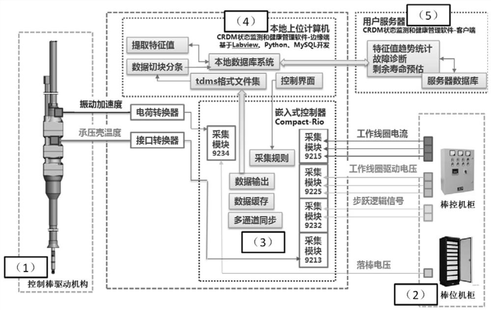
[0039] The invention provides a complete set of feasible technical methods for the state monitoring and health management of the control rod driving mechanism equipment, which can be used in the product bench test of the control rod driving mechanism, the debugging before the start-up of the nuclear power plant reactor and the test after the overhaul, and the long-t...


PUM


Abstract

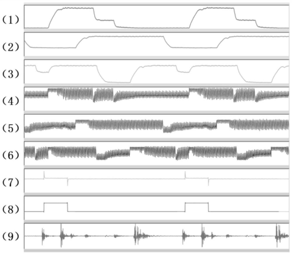
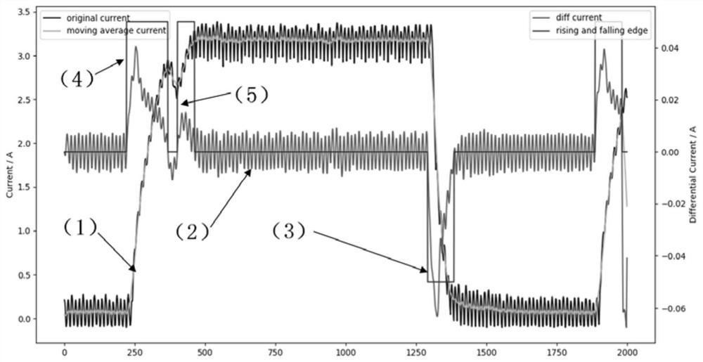
The invention discloses a nuclear reactor control rod driving mechanism monitoring and management system and method. The system comprises sensors (1 and 2), a data acquisition module (3), a data storage module (4), a local upper computer (5) and a server computer (6); the local upper computer (4) communicates with an embedded controller, completes data preprocessing and feature value extraction, and stores and manages the data in the two modes of an offline file and a local database; and the server computer (5) communicates with the local upper computer (4), calls standardized signal data entries, and completes characteristic value trend statistics and residual life calculation. A small number of sensors are additionally arranged on the basis of existing maturely-applied rod control rod position and control rod driving mechanism equipment of a nuclear power plant, and a feasible, accurate and reliable state monitoring and health management method and system meeting engineering requirements are provided for four component objects.

Description

technical field [0001] The invention belongs to the design field of a state monitoring system for nuclear power plant mechanical equipment, in particular to the field of state monitoring and health management of a reactor control rod driving mechanism. Background technique [0002] The reactor control rod drive mechanism is a mechanical device used to drive the control rod assembly to move up and down, and undertakes the important functions of reactor power regulation and emergency shutdown. The magnetic lifting type control rod driving mechanism is mainly composed of claw parts, coil parts, pressure-bearing shell parts and driving rod parts. [0003] First, the claw part is the core action mechanism of the control rod drive mechanism. The three sets of magnetic pole armature pairs drive the connecting rod, pin shaft, and claw to transmit the movement. The main failure mode is that the transmission structure is caused by factors such as foreign objects, wear, and rupture Th...

Claims


Application Information

Patent Timeline
IPC IPC(8): G21C17/10
CPCG21C17/10Y02E30/30
Inventor 周肖佳史骁辰王德斌柳树林孙丰诚袁璇刘刚王丰陈宇清白勇军佟辉毛飞徐峰
Owner 上海核工程研究设计院股份有限公司
Learn More