Incomplete transparent bottom plate shrinking type energy dissipater and energy dissipating method

An energy-dissipating and incomplete technology, applied in water conservancy projects, marine engineering, coastline protection, etc., can solve problems such as uneven distribution along the longitudinal and lateral directions, enhanced turbulence and air aeration, and aggravated flood discharge and atomization. Flood discharge atomization intensity and influence range, eliminating water fin phenomenon, reducing impact pressure effect

Pending Publication Date: 2020-09-22
LANZHOU UNIVERSITY OF TECHNOLOGY
View PDF5 Cites 0 Cited by
  • Summary
  • Abstract
  • Description
  • Claims
  • Application Information

AI Technical Summary

Problems solved by technology

[0003] The traditional retractable energy dissipation nose sill arranged on the dam body 4 is generally composed of a bottom plate 1 and side walls 2 on both sides. The structure is as follows: figure 1 and figure 2 As shown, the shrinkage energy dissipator forms the shrinkage section 3 with the help of the shrinkage of the side walls on both sides, which forces the water flow to deform, enhances turbulence and aeration, and forms a vertically and longitudinally diffused water flow pattern, but the upper edge of the discharge tongue appears horizontal The phenomena of curling, swinging left and right, and poor stability make the main body of the tongue entering the water concentrated, unevenly distributed in the vertical and horizontal directions, and impact the bottom of the pool, which also intensifies the atomization of flood discharge

Method used


Image

  • Incomplete transparent bottom plate shrinking type energy dissipater and energy dissipating method
  • Incomplete transparent bottom plate shrinking type energy dissipater and energy dissipating method
  • Incomplete transparent bottom plate shrinking type energy dissipater and energy dissipating method

Examples


Embodiment 1

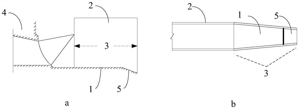
[0023] A non-completely air-permeable base plate retractable energy dissipator, such as image 3 As shown, it is arranged on the dam body 4 of the dam. The energy dissipator includes a bottom plate 1 and side walls 2 arranged on two opposite sides on the bottom plate 1. The two side walls 2 on the side of the discharge hole of the energy dissipator are symmetrically narrowed and The contraction section 3 is formed, and the energy dissipator also includes a support plate 5 arranged at the bottom of the drain hole and integrated with the bottom plate 1. The support plate 5 forms a broken-line non-permeable hollow shape to eliminate the lower edge of the drain tongue. water fins.

[0024] In the actual application process of the present invention, in the direction close to the lower side of the base plate, when the angle between the support plate and the base plate is 6-9° / the support plate is 1 / 6-1 / 5 of the total length of the contraction section , the supporting plate 5 consti...

Embodiment 2

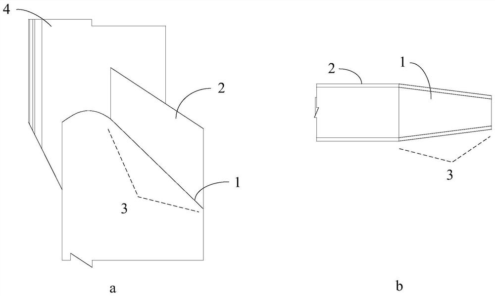
[0030] A non-completely air-permeable base plate retractable energy dissipator, such as Figure 4 As shown, it is arranged on the dam body 4 of the dam. The energy dissipator includes a bottom plate 1 and side walls 2 arranged on two opposite sides on the bottom plate 1. The two side walls 2 on the side of the discharge hole of the energy dissipator are symmetrically narrowed and The contraction section 3 is formed, and the energy dissipator also includes a support plate 5 arranged at the bottom of the drain hole and integrated with the bottom plate 1. The support plate 5 forms a broken-line non-permeable hollow shape to eliminate the lower edge of the drain tongue. water fins.

[0031] In the actual application process of the present invention, in the direction close to the lower side of the base plate, when the angle between the support plate and the base plate is 6-9° / the support plate is 1 / 6-1 / 5 of the total length of the contraction section , the supporting plate 5 const...


PUM


Abstract

The invention discloses an incomplete transparent bottom plate shrinking type energy dissipater and an energy dissipating method. The energy dissipater comprises a bottom plate and side walls arrangedon two opposite sides of the bottom plate. The two side walls of the energy dissipater shrink symmetrically to form a shrinking section. A drainage opening side of the energy dissipater is located atthe tail end of the shrinking section. The energy dissipater further comprises a layer board arranged at the bottom of the drainage opening and abutted to the bottom plate. The layer board forms a broken line type incomplete transparent figure to eliminate a water ring at the lower edge of a drainage tongue. The method improves a conventional energy dissipater to become the energy dissipater disclosed by the invention. The incomplete transparent bottom plate shrinking type energy dissipater can eliminate the water ring phenomenon effectively and derate influences of the drainage tongue to a downstream hydraulic structure of the drainage tongue to the greatest extent. In addition, the energy dissipater further can reduce the impact pressure to a plunge pool, reduce flood discharge atomization strength and scope of influence, and achieve the purposes of not only improving the energy dissipating efficiency, but also weakening atomization.

Description

technical field [0001] The invention belongs to the field of flood discharge and energy dissipation of water conservancy and hydropower projects, and in particular relates to a non-permeable floor shrinkable energy dissipation device and an energy dissipation method. Background technique [0002] Southwest my country is rich in hydropower resources, where the mountains are high and the valleys are steep, and the water flow has a large drop. The water conservancy and hydropower projects built in this area have complex geology, high and steep mountains on both banks, narrow river valleys, high seismic intensity, and large discharge flow from the dam body, which brings difficulties to the design of water conservancy projects, especially the layout of the dam body discharge structures. The technology of flood discharge and energy dissipation of the dam body is complicated and difficult. In water conservancy and hydropower projects, the problem of flood discharge and energy diss...

Claims


Application Information

Patent Timeline
Patent Type & Authority Applications(China)
IPC IPC(8): E02B8/06
CPCE02B8/06
Inventor 樊新建吴时强周辉侯慧敏崔艺馨王芳芳
Owner LANZHOU UNIVERSITY OF TECHNOLOGY
Why Eureka
Try Eureka