
Fault recognition method of vehicle speed reducer and vehicle control method and device

A vehicle control device and fault identification technology, which is applied in the direction of control devices, control drives, signal devices, etc., can solve problems such as vehicle inability to drive, inconvenient maintenance, shutdown, etc., and achieve the effect of improving safety and improving maintenance convenience

Active Publication Date: 2020-09-22
ZHENGZHOU YUTONG BUS CO LTD
View PDF5 Cites 0 Cited by
  • Summary
  • Abstract
  • Description
  • Claims
  • Application Information

AI Technical Summary

Problems solved by technology

[0005] The purpose of the present invention is to provide a vehicle decelerator fault identification method to solve the current problem of untimely identification of deceleration faults caused by artificially identifying vehicle decelerator faults; at the same time, the present invention also provides a vehicle control method to solve The current control method directly shuts down when the reducer fails, and the vehicle cannot drive, resulting in inconvenient maintenance; at the same time, the present invention also provides a vehicle control device to solve the problem that the current control device directly stops when the reducer fails, and the vehicle cannot drive. Problems that make maintenance inconvenient

Method used


Image

  • Fault recognition method of vehicle speed reducer and vehicle control method and device
  • Fault recognition method of vehicle speed reducer and vehicle control method and device
  • Fault recognition method of vehicle speed reducer and vehicle control method and device

Examples


Embodiment Construction

[0036] Vehicle control device embodiment:

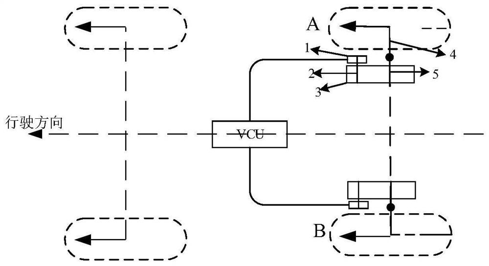
[0037] The vehicle control device proposed in this embodiment includes a gradient sensor, a vehicle speed sensor, an acceleration sensor, and a torque sensor and a rotational speed sensor for being arranged on each wheel motor, and the output ends of each sensor are connected to the signal input end of the controller. The signal output end of the controller controls and connects each wheel side motor.

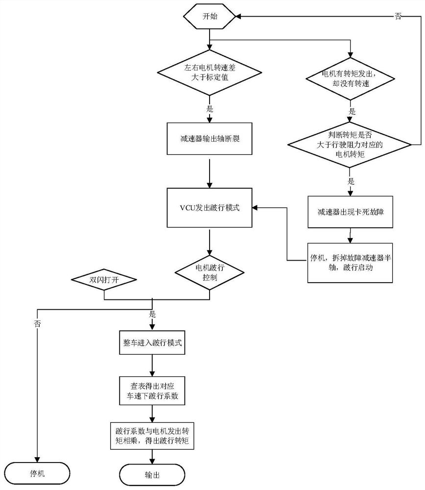
[0038] The main idea of ​​the present invention is that the controller judges the fault of the reducer through the signals of each sensor. The fault includes a stuck fault and a broken fault. The limp command controls the wheel side motor on the side where the reducer failure does not occur to output a limp torque, so that the whole vehicle enters the limp mode.

[0039] In this embodiment, the slope sensor is a gyroscope, and the controller is a vehicle controller (i.e. VCU). As other implementations, the slope sensor can also be an...


PUM


Abstract

The invention relates to a fault recognition method of a vehicle speed reducer and a vehicle control method and device, and belongs to the field of pure electric vehicle control. The fault recognitionmethod comprises the following steps of: 1) detecting a torque signal and a rotating speed signal of a wheel-side motor, and when the torque signal of the wheel-side motor is not zero, the rotating speed signal is zero, and the torque of the wheel-side motor is greater than a motor torque corresponding to driving resistance, judging that a speed reducer on the corresponding side of the wheel-sidemotor has a jamming fault; and 2) when a rotating speed difference value of the wheel-side motors on the two sides is larger than a calibration value, judging that the speed reducer on the corresponding side of the wheel-side motor with a high rotating speed has a fracture failure. The motor torque signals corresponding to the torque, the rotating speed and the driving resistance of each wheel-side motor are obtained, the fault of the vehicle speed reducer can be quickly judged through the relation between the signals, the situation that manual recognition is not timely and accurate is avoided, and the safety of the whole vehicle is further improved.

Description

technical field [0001] The invention relates to a fault identification method of a vehicle reducer, a vehicle control method and a device, and belongs to the field of pure electric vehicle control. Background technique [0002] At present, while automobiles bring convenience to people, they also pollute the environment. The development of automobiles has caused excessive consumption of resources, and energy shortage is an increasingly serious problem facing all mankind. Compared with traditional fuel vehicles, new energy vehicles have advantages in energy saving, environmental protection, and post-maintenance, so they are widely used around the world and are an inevitable trend in the future development of the automotive industry. [0003] As a kind of new energy vehicles, pure electric vehicles have become the mainstream trend of the development of the automobile industry. The pure electric vehicle is driven by a motor, and the engine is canceled. From the characteristics ...

Claims


Application Information

Patent Timeline
Patent Type & Authority Applications(China)
IPC IPC(8): B60W50/00B60L15/28B60Q1/46
CPCB60W50/00B60L15/28B60Q1/46B60W2050/0019Y02T10/72
Inventor 岳佳佳马英卢甲华谢俊峰
Owner ZHENGZHOU YUTONG BUS CO LTD
Learn More