Magnetic switch with fault diagnosis and diagnosis method

A fault diagnosis and magnetic switch technology, which is applied in the field of diagnostic switches, magnetic switches with fault diagnosis and diagnosis, to achieve the effects of reducing work intensity, timely diagnosis and troubleshooting, and low cost

Active Publication Date: 2022-01-14
SHANGHAI MEISHAN IRON & STEEL CO LTD
View PDF6 Cites 0 Cited by
  • Summary
  • Abstract
  • Description
  • Claims
  • Application Information

AI Technical Summary

Problems solved by technology

[0003] The present invention aims at the technical problems existing in the prior art, and provides a magnetic switch with fault diagnosis and a diagnostic method. The technical solution has a compact structure. Solve the problems encountered in the use of magnetic switches, and facilitate the rapid diagnosis and troubleshooting of faults

Method used


Image

  • Magnetic switch with fault diagnosis and diagnosis method
  • Magnetic switch with fault diagnosis and diagnosis method
  • Magnetic switch with fault diagnosis and diagnosis method

Examples


Embodiment 1

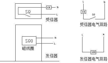
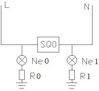
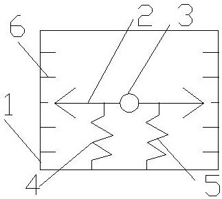
[0017] Embodiment 1: see figure 1 — image 3 , a magnetic switch with a fault diagnosis function for a signaling device with a fault diagnosis, the magnetic switch with a fault diagnosis includes a signaling device and a receiving device, the signaling device includes a transmitter body, and can display the working of the transmitter A status indicator light and a magnetic field strength indicator displaying the magnetic field strength; the trusted device includes a receiver body and an indicator light. The indicator light and the magnetic field strength indicator are installed on the transmitter body, wherein the indicator light is electrically connected to the transmitter body, and the magnetic field strength indicator pointer is perpendicular to the central axis of the transmitter body when the transmitter has no magnetic field signal. The body of the transmitter is an electromagnetic coil, which can generate a magnetic field signal to transmit the signal after being energ...


PUM


Abstract

The invention relates to a magnetic switch with fault diagnosis. The magnetic switch with fault diagnosis includes a sending device and a receiving device. The strength indicator of the magnetic field; the trusted device includes a receiver body and an indicator light. The technical solution provides a signaling device and a receiving device, and provides a diagnostic method to solve problems encountered in the use of the magnetic switch, and is convenient for rapid diagnosis and troubleshooting of faults.

Description

technical field [0001] The invention relates to a diagnostic switch, in particular to a magnetic switch with fault diagnosis and a diagnostic method, belonging to the technical field of electrical equipment. Background technique [0002] Magnetic proximity switches (magnetic switches) are widely used in industrial control electrical systems, and have the advantages of long sensing distance and low interference. Its structural diagram and electrical schematic diagram are as follows figure 1 shown. In actual use, there are the following problems: 1) After the failure of the signaling device, there will be a problem of not sending a magnetic signal or a magnetic signal is always present (residual magnetism), and the maintenance personnel cannot quickly find the cause of the failure: when there is no magnetism, they cannot Immediately determine whether it is caused by a power failure or an internal magnetic coil failure; when there is residual magnetism, it cannot be immediate...

Claims


Application Information

Patent Timeline
Patent Type & Authority Patents(China)
IPC IPC(8): H03K17/95G01R31/00G01R33/02
CPCH03K17/951H03K17/9517G01R31/00G01R33/02
Inventor 丁海泉
Owner SHANGHAI MEISHAN IRON & STEEL CO LTD
Why Eureka
Try Eureka