Overall Calibration Method of Measurement System in Transformer Test Station

A technology of measurement system and calibration method, applied in measurement devices, measurement of electrical variables, instruments, etc., can solve the problems of inability to display errors, slow speed, inability to calibrate measurement systems, etc., and achieve accurate comprehensive error, measurement comprehensive error, calibration Test the effect of fast speed

Active Publication Date: 2017-10-13
山东双益电气有限责任公司
View PDF8 Cites 0 Cited by
  • Summary
  • Abstract
  • Description
  • Claims
  • Application Information

AI Technical Summary

Problems solved by technology

[0002] The calibration method of the measurement system of the traditional transformer test station is generally: to calibrate the voltage transformer, current transformer and measuring instrument respectively. This calibration method plays a role in the calibration of the measurement system of the transformer test station, but it also has The following shortcomings or deficiencies: ① cannot truly reflect the comprehensive error of the measurement system, especially the error at low power factor; ② cannot display the error caused by the wrong connection of the connecting cable; The error caused by the increase of impedance caused by insurance, etc. and the error caused by the mismatch between the real impedance of the transformer and the nominal impedance cannot be displayed; ④ cannot calibrate the imported measurement system; ⑤ slow speed and low efficiency; ⑥ cannot test the transformer as a whole Station measurement system for calibration

Method used


Image

  • Overall Calibration Method of Measurement System in Transformer Test Station
  • Overall Calibration Method of Measurement System in Transformer Test Station

Examples


Embodiment Construction

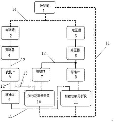
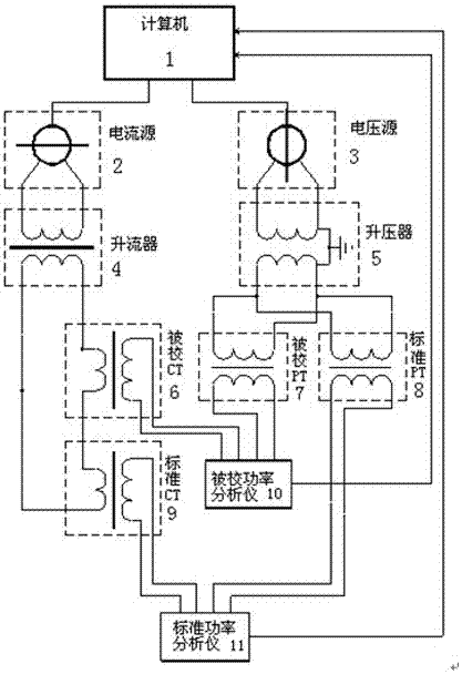
[0016] refer to Figure 1-Figure 2 , an overall calibration method for a transformer test station measurement system, including a computer 1, a current source 2, a voltage source 3, a current booster 4, a booster 5, a calibrated CT6, a calibrated PT7, a standard PT8, a standard CT9, a calibrated Power analyzer 10 and standard power analyzer 11. The computer 1 is connected to one end of the current source 2, the voltage source 3, the power analyzer 10 to be calibrated, and the power analyzer 11 to be calibrated, and the other end of the power analyzer 10 to be calibrated is respectively connected to the CT6 to be calibrated and the PT7 to be calibrated. The other end of the power analyzer 11 is connected to the standard CT9 and the standard PT8 respectively, the current source 2 is connected to the current booster 4, the CT6 to be calibrated and the standard CT9 in sequence, and the voltage source 3 is connected to the booster 5 in sequence, The booster 5 is connected with the...


PUM


Abstract

A method for calibrating the overall measurement system of a transformer test station, including a computer, a current source, a voltage source, a current booster, a booster, a calibrated CT, a calibrated PT, a standard PT, a standard CT, a calibrated power analyzer, and a standard power Analyzer. The computer is respectively connected to one end of the current source, the voltage source, the power analyzer to be calibrated and the standard power analyzer, and the other end of the power analyzer to be calibrated is respectively connected to the CT to be calibrated and the PT to be calibrated. The other end is connected to the standard CT and standard PT respectively, the current source is connected to the current booster, the CT to be calibrated and the standard CT in sequence, the voltage source is connected to the booster in sequence, and the booster is connected to the PT to be calibrated and the standard CT in sequence. Standard PTs are connected. The invention has the characteristics of accurately measuring the comprehensive error of the measurement system of the transformer test station, quickly judging the failure of the measurement system of the transformer test station, calibrating the new electronic measurement system, and performing an overall inspection of the newly produced transformer test station measurement system. It is widely used in transformers. It is used in the overall calibration process of the measurement system of the test station.

Description

Technical field: [0001] The invention relates to a method for calibrating a measurement system of a transformer test station, in particular to a method for calibrating an overall measurement system of a transformer test station. Background technique: [0002] The calibration method of the traditional measurement system of the transformer test station is generally: to calibrate the voltage transformer, current transformer and measuring instrument respectively. This calibration method plays a role in the calibration of the measurement system of the transformer test station, but it also has The following shortcomings or deficiencies: ① cannot truly reflect the comprehensive error of the measurement system, especially the error at low power factor; ② cannot display the error caused by the wrong connection of the connecting cable; The error caused by the increase of impedance caused by insurance, etc. and the error caused by the mismatch between the real impedance of the transfor...

Claims


Application Information

Patent Timeline
Patent Type & Authority Patents(China)
IPC IPC(8): G01R35/00
Inventor 于冠学胡观伟于涛姚树现
Owner 山东双益电气有限责任公司
Why Eureka
Try Eureka