Energy-saving and environment-friendly new energy electric appliance cabinet structure and energy-saving method thereof

An energy-saving, environment-friendly and new energy technology, which is applied in the fields of energy-saving of new energy electrical cabinets, energy-saving and environmental protection of new energy electrical cabinet structures, energy-saving and environmental protection of new energy electrical cabinet structures, can solve problems such as single function, leakage, and no power generation function. To achieve the effect of avoiding excessive water accumulation

Pending Publication Date: 2020-09-18
沈飞轩
View PDF0 Cites 1 Cited by
  • Summary
  • Abstract
  • Description
  • Claims
  • Application Information

AI Technical Summary

Problems solved by technology

[0003] The power distribution control cabinets in the prior art have a single function for control or power distribution, but they do not have any power generation function, and their structures are all square structures, which are often erected on high places or on the ground. However, in the rainy season, the accumulated water will overflow the power distribution cabinet and cause electricity leakage. Secondly, in the case of energy shortage and diversified energy production, if the power distribution cabinet has the function of saving energy and using new energy to generate electricity for products that can be seen everywhere It will provide a very energy-saving effect for the surrounding street lamps and other circuit equipment, and also save the power load of the city grid. Therefore, an environmentally friendly new energy electrical cabinet structure and its energy-saving method are designed to optimize the above problems

Method used


Image

  • Energy-saving and environment-friendly new energy electric appliance cabinet structure and energy-saving method thereof
  • Energy-saving and environment-friendly new energy electric appliance cabinet structure and energy-saving method thereof
  • Energy-saving and environment-friendly new energy electric appliance cabinet structure and energy-saving method thereof

Examples


Embodiment Construction

[0039] In order to make the technical solutions of the present invention clearer and clearer to those skilled in the art, the present invention will be further described in detail below in conjunction with the examples and accompanying drawings, but the embodiments of the present invention are not limited thereto.

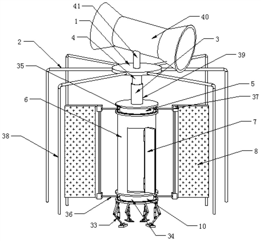
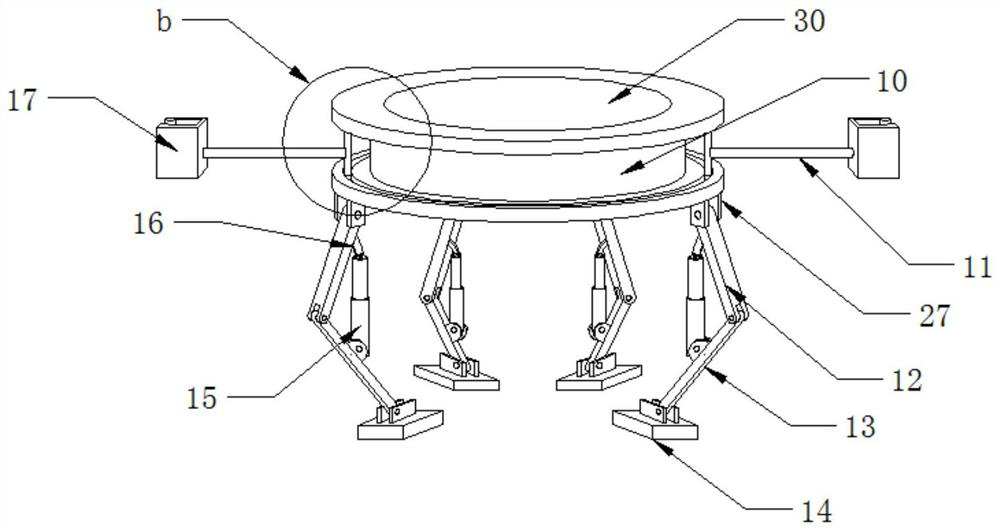
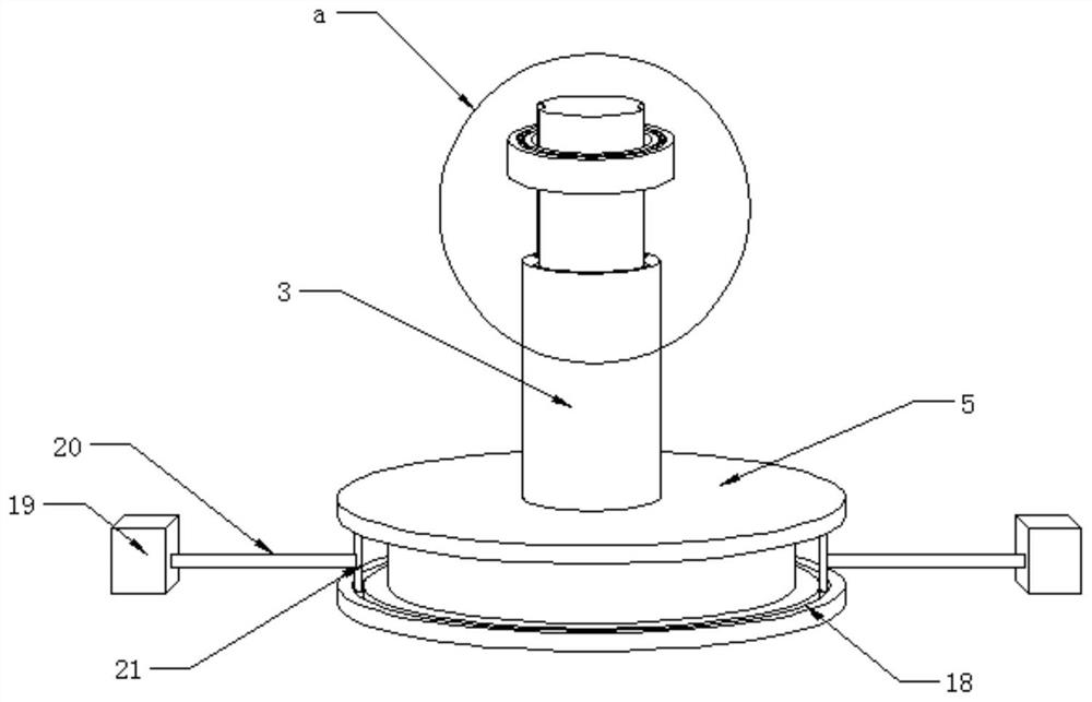
[0040] like Figure 1-Figure 12 As shown, the structure of an energy-saving and environment-friendly new energy electrical cabinet provided in this embodiment includes a housing 6, which is a cylindrical structure, and one side of the housing 6 is hinged with a door panel 7, and the top of the housing 6 slides The limit assembly is equipped with a top cover assembly 35 that can rotate on the top of the housing 6. The top cover assembly 35 is provided with a second rotating clamping assembly 37 that can move around the top cover assembly 35. The bottom of the housing 6 is equipped with a base assembly. 34, the base assembly 34 is provided with a first rotating clamp...


PUM


Abstract

The invention discloses an energy-saving and environment-friendly new energy electric appliance cabinet structure and an energy-saving method thereof, which belong to the technical field of new-energyelectrical cabinets. Strong thrust is generated to choke blades under the action of wind power, and a first rotary clamping assembly and a second rotary clamping assembly are driven to rotate on a base assembly and a top cover assembly respectively; mechanical energy generated by rotation drives a generator to generate electricity through a rotating rod; solar energy is obtained through a solar panel laid on the choke blades and converted into electric energy to supply power to a storage battery installed in the shell. When it is detected that the water level rises, an electric hydraulic cylinder is started to push a first hinge rod and a second hinge rod to expand by an angle to enable the shell to rise, the shell rises to drive the top cover to rise, then an outer fixing pipe is drivento rise on the outer side of an inner sliding pipe, and the problem of excessive accumulated water caused by excessive rainwater is solved.

Description

technical field [0001] The present invention relates to a new energy electrical cabinet, in particular to an energy-saving and environment-friendly new energy electrical cabinet structure, the invention also relates to a new energy electrical cabinet energy-saving method, in particular to an energy-saving and environmentally friendly new energy electrical cabinet structure energy-saving method, It belongs to the technical field of new energy electric cabinets. Background technique [0002] The control cabinet is to assemble the switchgear, measuring instrument, protective device and auxiliary equipment in the closed or semiclosed metal cabinet or on the screen width according to the requirements of electrical wiring. And the safety of the surrounding equipment, the circuit can be connected or broken by manual or automatic switch during normal operation, and the circuit can be cut off or alarmed by means of protective electrical appliances in case of failure or abnormal opera...

Claims


Application Information

Patent Timeline
IPC IPC(8): H02B1/30H02B1/56H02B1/50H02J7/35
CPCH02B1/30H02B1/505H02B1/565H02J7/35Y02E10/76
Inventor 沈飞轩
Owner 沈飞轩
Why Eureka
Try Eureka