A floor drain structure that automatically adapts to the drainage pressure

A technology of drainage pressure and automatic adaptation, applied in drainage structures, waterway systems, water supply devices, etc., can solve the problems that the size affects the cleanliness and beauty of the ground, and there are potential safety hazards, so as to avoid low drainage efficiency, good anti-blocking effect, The effect of preventing pulling out or breaking

Active Publication Date: 2022-07-26
ZHEJIANG IND POLYTECHNIC COLLEGE
View PDF13 Cites 0 Cited by
  • Summary
  • Abstract
  • Description
  • Claims
  • Application Information

AI Technical Summary

Problems solved by technology

[0002] Floor drains are not only decorative accessories for houses, but also drainage parts for outdoor places such as squares, terraces, and rooftops. For floor drains in such occasions, the anti-odor function is relatively secondary, and more important is the anti-lost, rainwater or accumulation of accessories. The drainage efficiency of water is particularly critical due to the uncontrollable rainfall. If large-diameter drainage structures such as manhole covers are used, on the one hand, there will be safety hazards, and at the same time, the cleanliness and beauty of the ground will be affected due to the large size

Method used


Image

  • A floor drain structure that automatically adapts to the drainage pressure
  • A floor drain structure that automatically adapts to the drainage pressure
  • A floor drain structure that automatically adapts to the drainage pressure

Examples


Embodiment Construction

[0028] The following are specific embodiments of the present invention and the accompanying drawings to further describe the technical solutions of the present invention, but the present invention is not limited to these embodiments.

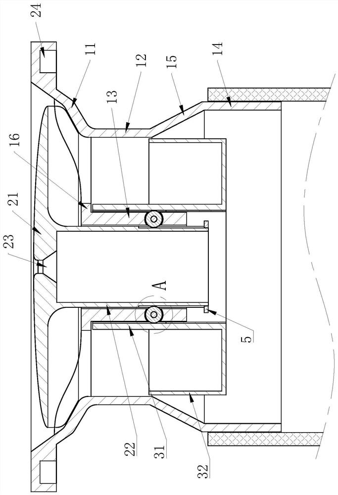
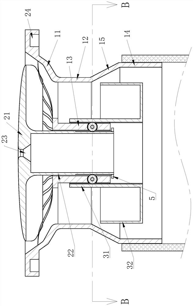
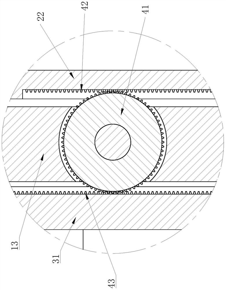
[0029] like figure 1 , figure 2 , image 3 , Figure 4 , Figure 5 and Image 6 As shown, it includes a floor drain body, an inner core and a sealing tube. The floor drain body includes a water guide cone 11, a water guide cone 12 connected to the lower end of the water guide cone 11, and a middle tube 13 located inside the water guide cone 12. The middle tube 13 and the water guide cone 11 The inner walls are connected by a number of spokes, and a water leakage groove is formed between the adjacent spokes; the inner core includes a cover plate 21 and a synchronization cylinder 22 located on the lower end surface of the cover plate 21, and the synchronization cylinder 22 is slidably connected to the inner side of the intermediate cylinder 1...


PUM


Abstract

The invention provides a floor drain structure that can automatically adapt to drainage pressure, and belongs to the technical field of water supply and drainage. It includes a floor drain main body, an inner core and a sealing tube. The floor drain body includes a water guide cone, a drain tube and a middle tube located inside the water tube. The middle tube and the inner wall of the water guide cone are connected by a number of spokes, and a leak is formed between the adjacent spokes. The water tank; the inner core includes a cover plate and a synchronizing cylinder located on the lower end face of the cover plate, the synchronizing cylinder is slidably connected to the inner side of the intermediate cylinder, and the lower surface of the cover plate outside the synchronizing cylinder has fins suitable for each leakage, and the adjacent fins are between A water leakage gap is formed; the sealing cylinder includes a sliding sleeve slidably connected to the outer side of the intermediate cylinder and a water-carrying cylinder located outside the sliding sleeve, the outer wall of the water-carrying cylinder is slidably connected to the inner wall of the lowering cylinder, and the lower end of the lowering cylinder has a connecting pipe with an inner diameter larger than that of the lowering cylinder , the connecting pipe is connected with the drain tube through a cone-shaped drain sleeve; the outer diameter of the cover plate is smaller than the inner diameter of the water guide cone. The invention has the advantages of good anti-blocking effect and the like.

Description

technical field [0001] The invention belongs to the technical field of water supply and drainage, and relates to a floor drain structure that can automatically adapt to drainage pressure. Background technique [0002] Floor drains are not only decorative accessories for houses, but also drainage parts for outdoor places such as squares, terraces, and rooftops. For floor drains in such occasions, the anti-odor function is relatively secondary, and the more important thing is the anti-lost, rain or accumulation of accessories. The drainage efficiency of water is affected by the uncontrollable rainfall, and drainage efficiency is particularly critical. If a large-aperture drainage structure such as a manhole cover is used, on the one hand, there will be potential safety hazards, and at the same time, the large size will affect the cleanliness and beauty of the ground. SUMMARY OF THE INVENTION [0003] The purpose of the present invention is to provide a floor drain structure ...

Claims


Application Information

Patent Timeline
Patent Type & Authority Patents(China)
IPC IPC(8): E03F5/04E03F5/06
CPCE03F5/0407E03F5/041E03F5/06E03F2005/0416E03F2005/068
Inventor 翁窈瑶
Owner ZHEJIANG IND POLYTECHNIC COLLEGE
Why Eureka
Try Eureka