
A cable protection device for electrical machinery equipment

A technology of electric machinery and protective devices, applied in the direction of electrical components, etc., can solve the problems of endangering the safety of vehicles and personnel, poor anti-drop effect, difficult maintenance, etc., and achieve the effect of preventing excessive water accumulation

Active Publication Date: 2020-07-21
STATE GRID CORP OF CHINA +1
View PDF6 Cites 0 Cited by
  • Summary
  • Abstract
  • Description
  • Claims
  • Application Information

AI Technical Summary

Problems solved by technology

The development of power equipment cannot be separated from the development support of the power insulation protection industry. The lines of the cables are relatively dense, and rainwater will fall on the cables in rainy days. Once the insulation of the cables erected on both sides of the expressway is broken, it is easy to cause a short circuit, which not only makes maintenance difficult, but also endangers Safety of passing vehicles and people
[0003] A combined weak current cable protection device disclosed in the Chinese invention patent application publication CN207183963U, although the combined weak current cable protection device, by adding a partition wall, can not only meet the needs of various professional pipeline laying, but also avoid Because there are many types of pipelines that cause space interference, the efficiency of construction and operation and maintenance is greatly improved. By setting a partition plate in the cable cavity, the cable cavity is divided into multiple separate cavities to arrange different types of cables. The integrated pipeline can be well realized, and the design of the existing cable protection device is simply optimized, which is easy to produce and implement, greatly improves the efficiency of pipeline installation, laying and maintenance, and meets the needs of production. However, the combined Weak current cable protection device has the disadvantages of poor waterproof effect and poor anti-drop effect

Method used


Image

  • A cable protection device for electrical machinery equipment
  • A cable protection device for electrical machinery equipment
  • A cable protection device for electrical machinery equipment

Examples


Embodiment 1

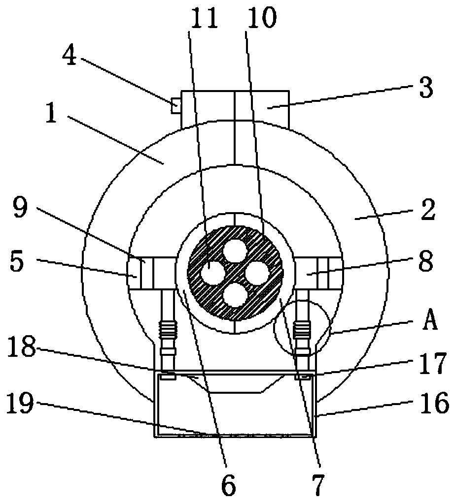
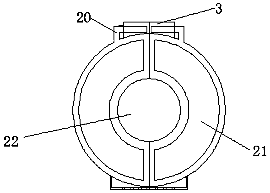
[0024] Wherein, the first cable protective shell 1 and the second cable protective shell 2 are both semicircular, and they are combined into a circle. After the first cable protective shell 1 and the second cable protective shell 2 are combined, there will be an opening at the bottom, and the opening is set There is a buffer block 16;

[0025] Both the first cable harness tube 6 and the second cable harness tube 7 are semicircular and assembled into a circle.

[0026] Because this protective device is not completely sealed, when it rains, raindrops can penetrate into the device, and the water hole 19 can prevent the accumulation of drops on the first support plate 5, and the raindrops can flow into the buffer block through the water hole 19.

[0027] An opening is left at the bottom of the assembled first cable shielding shell 1 and the second cable shielding shell 2 for installing a buffer block 16 .

[0028] The nut 17 can fix the buffer block 16 to effectively prevent the ...


PUM


Abstract

A cable protection device for electric mechanical equipment in accordance with that present invention, in particular to a cable protection device for electric mechanical equipment, include a first cable shield, one side of the first cable shield is provided with a second cable shield, The top of the first cable protective shell and the second cable protective shell are fixedly connected with a fixing block, one side of the fixing block is inserted with bolts, the first cable protective shell is fixedly connected with the second cable protective shell through bolts, and the inner wall of the first cable protective shell is fixedly connected with the first support plate. A cable protection device for electric mechanical equipment When the cable protective device falls to the ground, the buffer block can drive the support connecting rod to impact the support rod, and the spring can reduce the impact strength of the support connecting rod to the support rod, so as to achieve the purpose ofavoiding the cable protective device from falling to the ground and causing damage.

Description

technical field [0001] The invention relates to the technical field of electric equipment, in particular to a cable protection device for electric mechanical equipment. Background technique [0002] Power equipment mainly includes power generation equipment and power supply equipment. Power generation equipment is mainly power plant boilers, steam turbines, gas turbines, water turbines, generators and transformers, etc. Power supply equipment is mainly transmission lines, transformers and contactors of various voltage levels. etc. With the rapid development of my country's economy, electric power construction has developed by leaps and bounds. The development of power equipment cannot be separated from the development support of the power insulation protection industry. The lines of the cables are relatively dense, and rainwater will fall on the cables in rainy days. Once the insulation of the cables erected on both sides of the expressway is broken, it is easy to cause a sh...

Claims


Application Information

Patent Timeline
Patent Type & Authority Patents(China)
IPC IPC(8): H02G3/04
CPCH02G3/0481
Inventor 谢田徐拓沈忱周月乔邓明华郑韩蓉万付宝杜剑华彭彬彬明璇李言明胡春霞
Owner STATE GRID CORP OF CHINA
Learn More