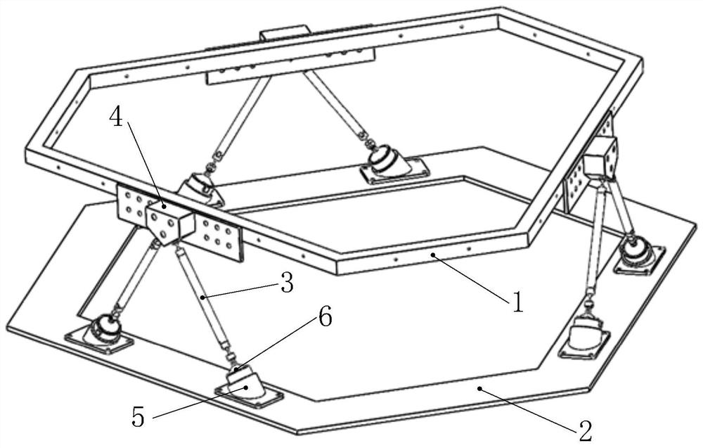
Optical effective load passive vibration isolation system

A payload and vibration isolation system technology that is applied to shock absorbers, motor vehicles, and vibration suppression adjustments. It can solve problems such as easy damage to components, and achieve the effects of low processing costs, convenient assembly, and simplified dynamic analysis and structure.

Inactive Publication Date: 2020-09-18
HARBIN INST OF TECH
View PDF15 Cites 1 Cited by
  • Summary
  • Abstract
  • Description
  • Claims
  • Application Information

AI Technical Summary

Problems solved by technology

[0005] Aiming at the problem that the components of the existing vibration isolation platform are easy to be damaged under the condition that

Method used


Image

  • Optical effective load passive vibration isolation system
  • Optical effective load passive vibration isolation system
  • Optical effective load passive vibration isolation system

Examples


Embodiment Construction

[0029] The following will clearly and completely describe the technical solutions in the embodiments of the present invention with reference to the accompanying drawings in the embodiments of the present invention. Obviously, the described embodiments are only some, not all, embodiments of the present invention. Based on the embodiments of the present invention, all other embodiments obtained by persons of ordinary skill in the art without creative efforts fall within the protection scope of the present invention.

[0030] It should be noted that, in the case of no conflict, the embodiments of the present invention and the features in the embodiments can be combined with each other.

[0031] The present invention will be further described below in conjunction with the accompanying drawings and specific embodiments, but not as a limitation of the present invention.

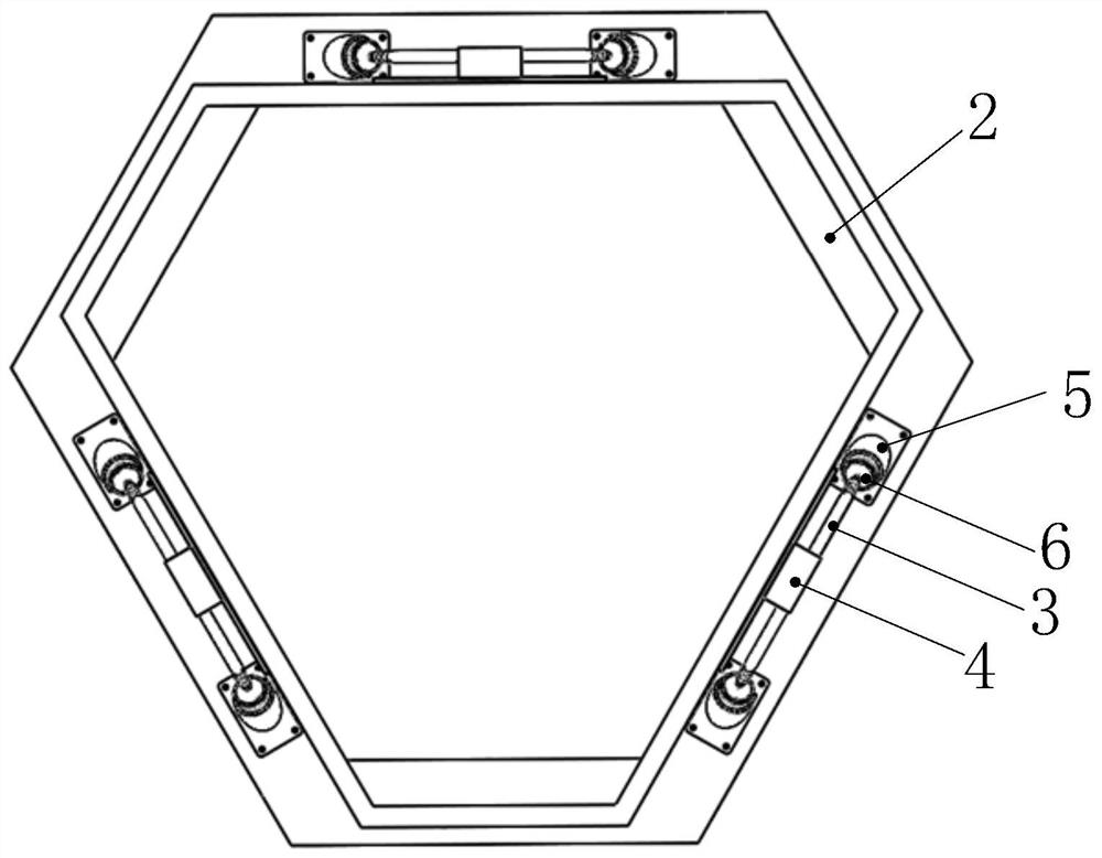
[0032] Such as Figure 1 to Figure 4 As shown, a passive vibration isolation system for an optical payload in t...


PUM


Abstract

The invention discloses an optical effective load passive vibration isolation system, and belongs to the technical field of spacecraft micro-vibration control. The problem that components of an existing vibration isolation platform are prone to be damaged under the condition that the ascending acceleration of a satellite is too high is solved. According to the system, the configuration is characterized in that three upper mounting supports are distributed and fixed to the side face of an upper platform, the positions of the three upper mounting supports are on the same circle, and the centralangle formed by every two upper mounting supports is 120 degrees; six eddy current damper mounting bases are fixed to a lower platform; six supporting legs are divided into three groups, the top endsof the two supporting legs in one group are fixed on the same upper mounting support, one eddy current damper is arranged at the bottom end of each supporting leg, and the eddy current dampers are fixed in eddy current damper mounting bases on the lower platform; and the plane where the two supporting legs in one group are located are perpendicular to the plane where the upper platform is locatedand the plane where the lower platform is located at the same time, the eddy current damper mounting bases at the bottoms of the three groups of supporting legs are distributed on the three edges of aregular triangle, and the eddy current damper mounting bases at the bottoms of one group of supporting legs are located on the same edge.

Description

technical field [0001] The invention relates to a vibration isolation system, in particular to a passive vibration isolation system for an optical payload, and belongs to the technical field of spacecraft micro-vibration control. Background technique [0002] During the in-orbit operation of the spacecraft, the rotation of the rotating parts on the spacecraft, the stepping motion of the drive mechanism, the operation of the thruster, the mechanical movement of the compressor and other components, the vibration of the large flexible structure itself, and the thermal deformation induced when entering and leaving the shadow area, etc. Both will cause the spacecraft to produce a vibration response with a small vibration amplitude and a wide frequency range, that is, micro vibration. The problem of microvibration widely exists in various spacecraft, but because of its small vibration amplitude, it has little impact on most space activities, and most of them are not considered. H...

Claims


Application Information

Patent Timeline
IPC IPC(8): F16F15/03B64G1/22
CPCF16F15/035B64G1/22F16F2222/06B64G1/228
Inventor 柳超然于开平唐介廖宝鹏胡蓉平
Owner HARBIN INST OF TECH
Why Eureka
Try Eureka