Robot wrist joint

A robot wrist and joint technology, applied in the directions of manipulators, manufacturing tools, joints, etc., can solve problems such as insufficient stability, three degrees of freedom cannot intersect at one point, and reduce control accuracy, and achieve simplified dynamic models and control algorithms. , Eliminate the problem of motion control coupling, the effect of simple hardware system

Inactive Publication Date: 2013-09-18
NINGBO UNIV
View PDF7 Cites 7 Cited by
  • Summary
  • Abstract
  • Description
  • Claims
  • Application Information

AI Technical Summary

Problems solved by technology

[0003] The structure of the current mainstream three-degree-of-freedom robot wrist joint is composed of two cylinders, which respectively control two degrees of freedom. The connecting rod on the wrist joint and the manipulator provides a rotational degree of freedom. The internal power is transmitted through the meshing of the gears, but the gear transmission limits the transmission distance of the torque to a large extent. When installing the motor, the motor cannot be placed far away, because the gear transmission is not suitable for long-distance transmission, and many Stage gear transmission will reduce control accuracy
Although the current wrist joint structure is very mature in the industry, the structure of this series mode is not compact enough, the displacement control coupling is significant, and the three degrees of freedom cannot intersect at one point, so that the center of rotation cannot coincide with the center of gravity of the moving part , so the dynamic model of the traditional wrist joint is complicated, the coupling of the kinematic model is serious, the cumulative control error is large, and the vibration during work is relatively large, and the stability is not good enough.

Method used


Image

  • Robot wrist joint
  • Robot wrist joint
  • Robot wrist joint

Examples


Embodiment Construction

[0014] The present invention will be further described in detail below in conjunction with the accompanying drawings and embodiments.

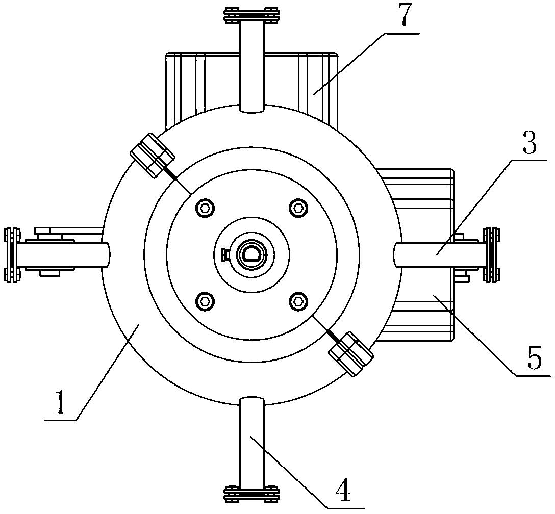
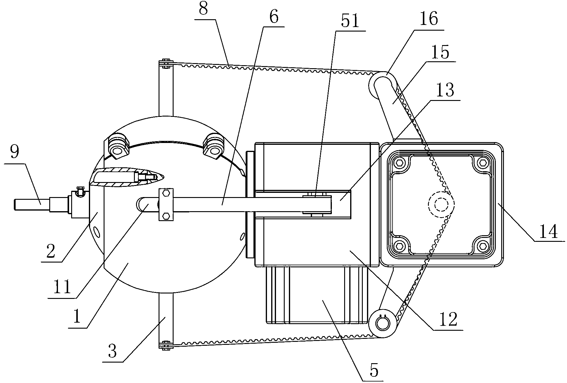
[0015] As shown in the figure, a robot wrist joint includes a spherical housing 1 and a spherical revolving body 2. The housing 1 is set on the revolving body 2, and the revolving body 2 is fixedly equipped with an X-direction control rod group and a Y-direction control rod group. Rod group, the X-direction control rod group includes two X-direction control rods 3 on the same straight line and opposite to each other, and the Y-direction control rod group includes two Y-direction control rods 4 on the same straight line and opposite to each other The housing 1 is provided with guide grooves 11 at positions corresponding to the X-direction control rod 3 and the Y-direction control rod 4, and the X-direction control rod 3 and the Y-direction control rod 4 are respectively screwed with the rotary body 2 and protrude out from it. The guide groove 1...


PUM


Abstract

The invention discloses a robot wrist joint, which is characterized by comprising a spherical housing and a spherical revolving body sleeved with the housing, wherein two perpendicular groups of control rods are fixedly arranged on the revolving body; guide grooves are formed in the housing at the position corresponding to the control rod groups; the control rod groups extend out of the guide grooves; a control rod group rotation driving device is fixedly arranged on the housing; a connecting rod connected with a manipulator is arranged on the revolving body and is perpendicular to the plane where the two control rod groups are positioned; and a connecting rod rotation driving device is fixedly arranged in the revolving body. The robot wrist joint has the advantages that the revolving body is spherical, and three freedom degrees of the wrist joint are realized in the revolving body, so as to allow the three freedom degrees to be intersected at one point and then form a parallel structure for three-coordinates motion control; and due to system design, the gravity center of the control motion part is completely superposed with the center of rotation, so that when the wrist joint works, a control system, a software system and a hardware system are simple, the control precision is high, and the stability is good and the vibration is small when the wrist joint is in operation.

Description

technical field [0001] The invention relates to components of a robot, in particular to a robot wrist joint. Background technique [0002] The wrist joint is an important part of the interconnection between the robot arm and the manipulator. Its main function is to adjust and change the position and three-dimensional posture of the manipulator in three-dimensional space. Therefore, the flexibility of the wrist joint in space movement and movement in space The range directly affects the overall function and performance of the robot at work. [0003] The structure of the current mainstream three-degree-of-freedom robot wrist joint is composed of two cylinders, which respectively control two degrees of freedom. The connecting rod on the wrist joint and the manipulator provides a rotational degree of freedom. The internal power is transmitted through the meshing of the gears, but the gear transmission limits the transmission distance of the torque to a large extent. When insta...

Claims


Application Information

Patent Timeline
Patent Type & Authority Applications(China)
IPC IPC(8): B25J17/02
Inventor 詹建明陈伟胡利永王钢明曾云川赵钰
Owner NINGBO UNIV
Why Eureka
Try Eureka