
Oil-gas separation type variable oil hole combined crash-resistant buffer

A separate buffer technology, applied in the direction of gas-hydraulic shock absorbers, shock absorbers, shock absorbers, etc., can solve the problems of poor flexibility, limited stroke, and the impact of the total energy absorption of the buffer, so as to improve the buffering efficiency , Improve the bearing capacity, and have a wide range of applications

Inactive Publication Date: 2020-09-18
NANJING UNIV OF AERONAUTICS & ASTRONAUTICS
View PDF6 Cites 2 Cited by
  • Summary
  • Abstract
  • Description
  • Claims
  • Application Information

AI Technical Summary

Problems solved by technology

[0003] Conventional landing gear with single-stage double-cavity buffer structure design, because its take-off and landing buffer and crash-resistant buffer share the same buffer stroke of the piston rod, the stroke that can actually be used for crash-resistant buffer is very limited, and it is difficult to meet the needs of current aircraft. Crash resistance performance requirements
[0004] Conventional oil-air buffers usually adopt the oil-air mixed form of fixed-sized oil holes. When using this type of buffer, it is necessary to ensure that the oil chamber is below the air chamber, which has poor flexibility and cannot be applied to some specific situations that require the side of the air chamber. The case below the buffer
The oil hole with a fixed size causes the flow rate of the oil hole to be the same at each moment in the working state of the buffer, and it is not convenient to adjust the size of the buffer force to adapt to specific working conditions and protection objects
[0005] Commonly used crash-resistant buffers relying on the material collapse method, such as metal honeycomb buffers and foamed aluminum buffers, have the characteristics of light weight, but after the material is compacted, it occupies a part of the buffer stroke, which has a large impact on the total energy absorption of the buffer. In addition, it is difficult for this type of buffer to guarantee the consistency of buffer characteristics of different batches of products

Method used


Image

  • Oil-gas separation type variable oil hole combined crash-resistant buffer
  • Oil-gas separation type variable oil hole combined crash-resistant buffer
  • Oil-gas separation type variable oil hole combined crash-resistant buffer

Examples


Embodiment Construction

[0023] The technical solutions of the present invention will be described in detail below in conjunction with the accompanying drawings.

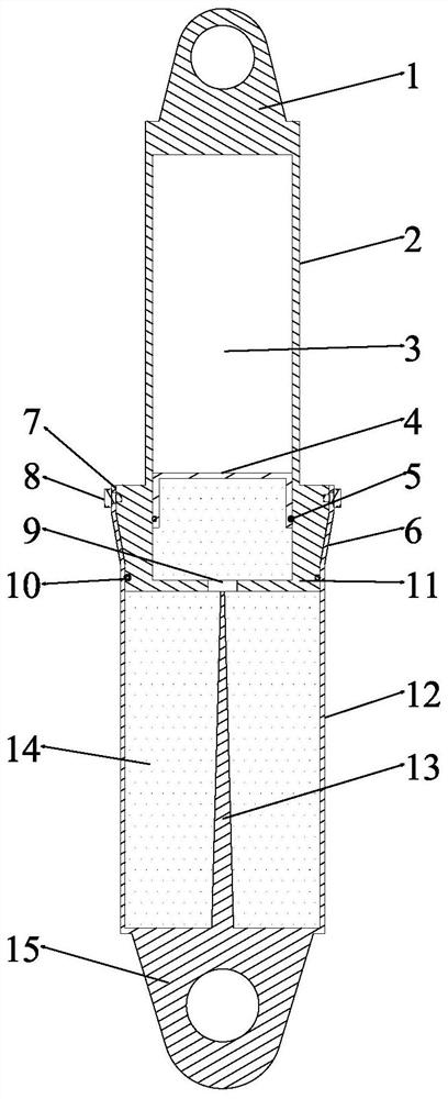
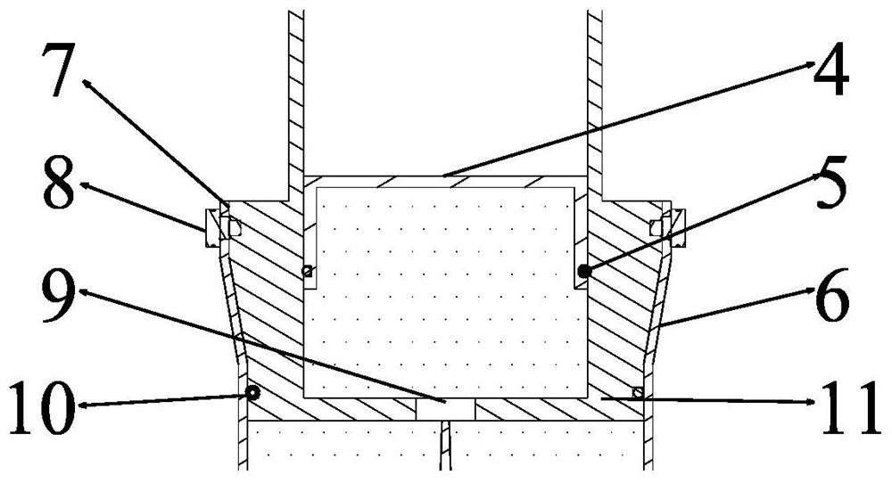
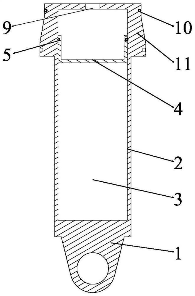
[0024] Such as Figure 1-3 As shown, the present invention has designed an oil-air separation type variable oil hole composite anti-crash buffer, including a piston rod assembly and a metal expansion cylinder. The piston rod assembly includes a piston rod 2 , a floating piston 4 and a conical head 11 . The lower end of the piston rod 2 is in contact with the cone head 11 and fixed by the screw 8. The space formed by the piston rod 2 and the cone head 11 is used as the air chamber 3. The floating piston 4 is placed in the air chamber 3 and can float up and down. The cone head There is an oil hole 9 at the center of the bottom of 11, and the oil hole 9 can be scaled according to the force. The metal expansion cylinder includes a sizing guide belt 7, a diameter reducing belt 6 and an expansion cylinder body 12, and the sizing guide belt 7, t...


PUM


Abstract

The invention discloses an oil-gas separation type variable oil hole composite crash-resistant buffer. The buffer comprises a piston rod assembly and a metal expansion cylinder, the piston rod assembly comprises a piston rod, a floating piston and a conical head, the lower end of the piston rod makes contact with the conical head and is fixed through a screw, a space defined by the piston rod andthe conical head serves as an air cavity, the floating piston is arranged in the air cavity and can float up and down, an oil hole is formed in the center of the bottom of the conical head, and the oil hole can be shrunk according to stress; the metal expansion cylinder comprises a sizing guide belt, a reducing belt and an expansion cylinder body, the sizing guide belt, the reducing belt and the expansion cylinder body are sequentially connected and wrap the conical head, the outer diameter of the upper end of the conical head is larger than the inner diameter of the expansion cylinder body, the inner space of the expansion cylinder body serves as an oil cavity, an oil needle is arranged in the oil cavity, the oil needle is inserted into the oil hole to change the size of the oil hole whenthe buffer works. During working, the metal expanding energy-absorbing buffer and the oil-gas separation type buffer play roles at the same time, so that the buffering efficiency and the crash resistance of the aircraft are effectively improved.

Description

technical field [0001] The invention belongs to the field of aircraft take-off and landing devices, and in particular relates to a crash-resistant buffer. Background technique [0002] With the development of various types of aircraft and the diversification of their functions, different mission requirements have also put forward corresponding requirements for the take-off and landing devices of the aircraft. In mission environments such as helicopters falling at a relatively high speed, landing of interstellar probes, and recovery of aerospace vehicles, it is required that the take-off and landing device can absorb the power of the aircraft when it lands and reduce the impact overload, so as to ensure the safety of the occupants and related issues during landing. normal operation of the device. Therefore, improving the crash resistance of landing gear buffers will increase the survival rate of pilots in crashes and the successful landing rate of related aircraft and lander...

Claims


Application Information

Patent Timeline
Patent Type & Authority Applications(China)
IPC IPC(8): F16F13/00F16F9/06F16F9/36F16F9/48F16F9/49F16F9/54F16F7/09F16F7/12B64C25/58B64C25/60
CPCB64C25/58B64C25/60F16F7/095F16F7/128F16F9/061F16F9/067F16F9/368F16F9/483F16F9/49F16F9/54F16F13/002F16F2222/04F16F2222/12F16F2222/126F16F2230/0005F16F2232/08
Inventor 魏小辉陈虎房兴波谢欣宏聂宏
Owner NANJING UNIV OF AERONAUTICS & ASTRONAUTICS
Learn More