Air purification device for automobile

An air purification device and automobile technology, applied in air treatment equipment, vehicle maintenance, vehicle parts, etc., can solve the problems of inability to purify the air, concentration, limited space, etc., so as to improve the purification effect, improve the purification efficiency, and improve the work efficiency. Effect

Inactive Publication Date: 2020-09-18
李水文
View PDF1 Cites 0 Cited by
  • Summary
  • Abstract
  • Description
  • Claims
  • Application Information

AI Technical Summary

Problems solved by technology

An air purification device for new energy vehicles in the above-mentioned patent has the following disadvantages: when the existing device purifies the air, the air will gather together and enter the interior of the device, and due to the limited internal space of the device, it may be Because the gas distribution is too concentrated, the device cannot effectively purify the air

Method used


Image

  • Air purification device for automobile
  • Air purification device for automobile
  • Air purification device for automobile

Examples


Embodiment 1

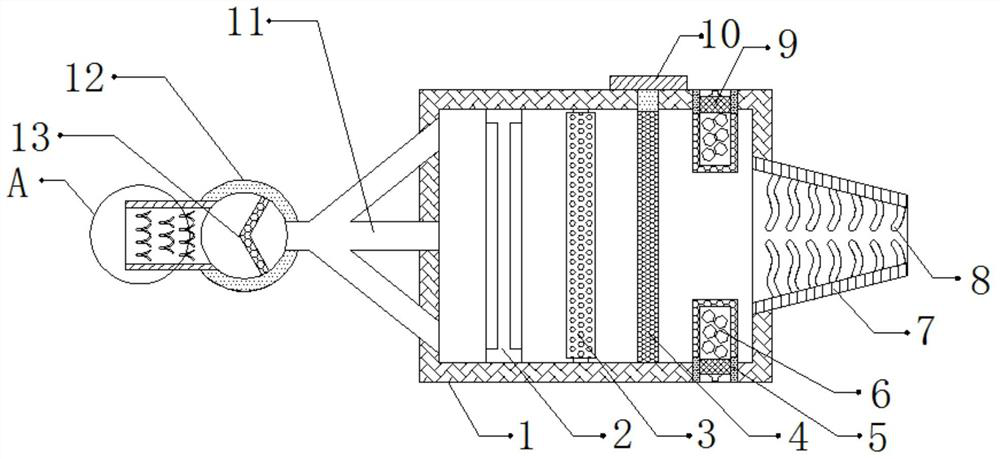
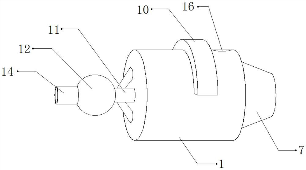
[0029] refer to Figure 1-3 , an air purification device for automobiles, comprising a treatment tank 1, an air guide tube 11 is arranged on one side of the treatment tank 1, and the shape of the air guide tube 11 is umbrella-shaped, which can facilitate the shunting treatment of the air, so as to improve the performance of the device. The purification efficiency of the air prevents the poor fluidity of the internal gas of the device due to the gas gathering together, thereby affecting the working efficiency of the device. The outer wall of the air duct 11 is provided with an air storage tank 12, and the air storage tank 12 The inner wall of the tank 1 is connected with a filter plate 13 by bolts, an air inlet is provided on one side outer wall of the air storage tank 12, and an air inlet pipe 14 is arranged on the inner wall of the air inlet, and an air inlet pipe 14 is arranged on the outer wall of the processing tank 1 away from the side of the air guide pipe 11 Exhaust pip...

Embodiment 2

[0038] refer to Figure 4 , an air purification device for automobiles. Compared with Embodiment 1, the outer wall of the bottom of the treatment tank 1 is provided with a plurality of slagging outlets, and the inner wall of the slagging outlet is provided with a sealing plug 19. The top of the treatment tank 1 The outer wall is bonded with a protective pad 18, and the top outer wall of the protective pad 18 is connected with a vibrating motor 17 by bolts, which can facilitate the cleaning of the inside of the device, so as to improve the purification effect of the device and prevent the inside of the device from being blocked to purify the air make an impact.

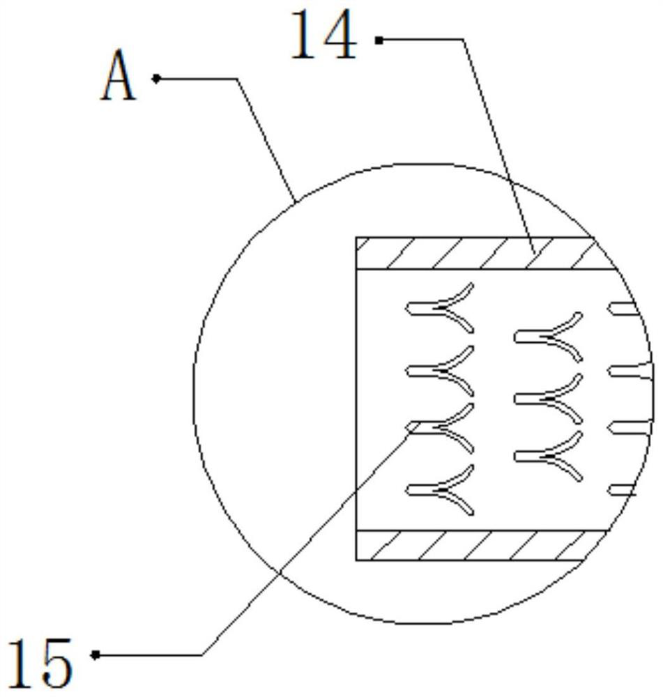
[0039] Working principle: When in use, install the device inside the car, the air inside the car will enter the inside of the air storage tank 12 through the intake pipe 14, and the floating objects can be blocked by the stopper 15, so as to purify the air , the shape of the stopper 15 is a "person" shape, which can s...


PUM


Abstract

The invention discloses an air purification device for an automobile. The device comprises a treatment tank; an air guide pipe is arranged on the outer wall of one side of the treatment tank; and theair guide pipe is in an umbrella shape. An air storage tank is arranged on the outer wall of one side of the air guide pipe; the inner wall of the air storage tank is fixedly connected with a filter plate; an air inlet is formed in the outer wall of one side of the air storage tank, an air inlet pipe is arranged on the inner wall of the air inlet, an exhaust pipe is arranged on the side, away fromthe air guide pipe, of the outer wall of the treatment tank, the exhaust pipe is conical, an electrostatic dust collector is fixedly connected to the inner wall of the treatment tank, and a negativeion generator is fixedly connected to the inner wall of the treatment tank. According to the device, the influence on the working efficiency of the device due to poor fluidity of gas in the device canbe prevented, air in the device can be prevented from flowing back to the outside of the device, outside air can be prevented from flowing into the device, and the influence on air purification due to blockage in the device can be prevented.

Description

technical field [0001] The invention relates to the technical field of automobiles, in particular to an air purification device for automobiles. Background technique [0002] The interior space of the car is narrow and closed for a long time, so it is easy to breed bacteria and produce peculiar smell, resulting in a serious decline in the air quality in the car and endangering people's health. If people stay in this environment for a long time, they are prone to dizziness. Therefore, it is necessary to purify the air through an air purification device. [0003] After searching, the Chinese patent authorization number is CN208411368U, which discloses an air purification device for new energy vehicles, including a casing, and the two ends of the top of the casing are respectively provided with an air inlet pipe and an air outlet pipe, and the inside of the casing is fixed. A filter box is installed, and the filter box communicates with the air inlet pipe through the installat...

Claims


Application Information

Patent Timeline
IPC IPC(8): B60H3/00B60H3/06B60S1/64
CPCB60H3/0078B60H3/06B60S1/64
Inventor 李水文
Owner 李水文
Why Eureka
Try Eureka