
Clamping and positioning mechanism for polishing bent edges of filter tank body

A technology of clamping and positioning and filtering tanks, which is applied in the direction of machine tools, grinding machines, and grinding workpiece supports suitable for grinding the edge of workpieces. It can solve the problems of large manual labor and low efficiency, and achieve good results and firm clamping. , The effect of reducing the amount of manual labor

Pending Publication Date: 2020-09-18
共通(浙江)机械有限公司
View PDF7 Cites 0 Cited by
  • Summary
  • Abstract
  • Description
  • Claims
  • Application Information

AI Technical Summary

Problems solved by technology

[0002] Existing filter tanks are generally formed by bending and stamping steel plates. Generally, the top and sides of the tank will be formed with bent edges, and the edges of the bent edges will have burrs, which need to be deburred. The existing method is Manual deburring requires one hand to hold and fix, and the other hand to operate a grinder or polishing machine for polishing and deburring, which has low efficiency and a large amount of manual labor

Method used


Image

  • Clamping and positioning mechanism for polishing bent edges of filter tank body
  • Clamping and positioning mechanism for polishing bent edges of filter tank body
  • Clamping and positioning mechanism for polishing bent edges of filter tank body

Examples


Embodiment Construction

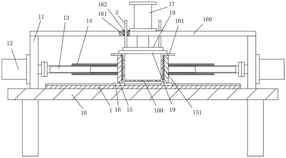
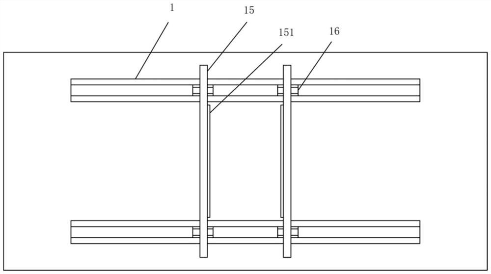
[0017] Examples, see e.g. Figure 1 to Figure 3 As shown in the figure, a clamping and positioning mechanism for grinding while bending the filter tank body includes a frame 10, and at least one guide rail 1 is fixed in the middle of the top surface of the top plate of the frame 10;

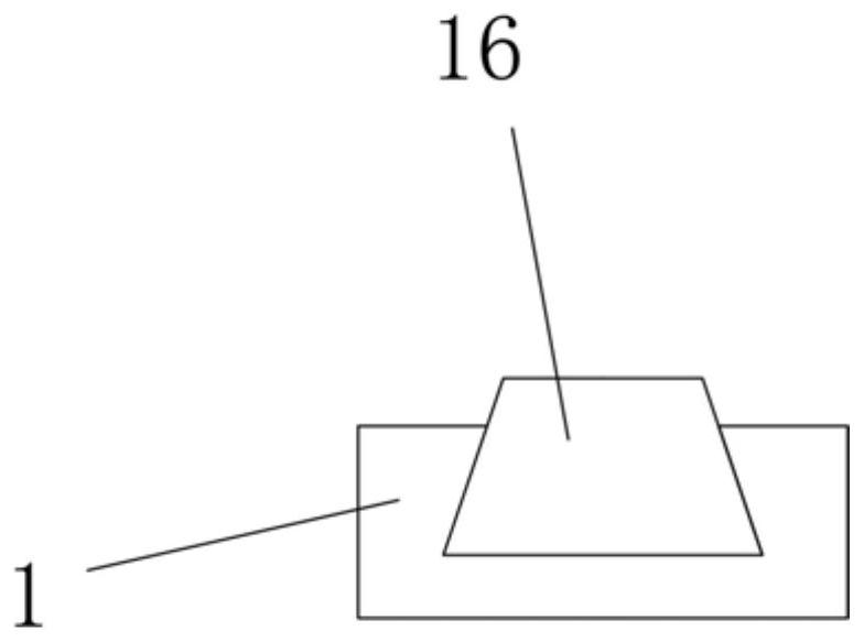
[0018] The left and right sides of the top plate of the frame 10 are fixed with vertical plates 11, the guide rail 1 is between the two vertical plates 11, and the output shaft of the mobile motor 12 is fixed on the outer wall of the vertical plate 11 to pass through. The vertical plate 11 is connected with a transverse screw rod 13 through a shaft coupling, and the transverse screw sleeve 14 is screwed on the horizontal screw rod 13. The end of the horizontal screw sleeve 14 is fixed with a compression plate 15, and the bottom surface of the compression plate 15 is fixed with a slide plate. block 16, the slider 16 is inserted in the chute of the guide rail 1, the filter tank body 100 to be proce...


PUM


Abstract

The invention discloses a clamping and positioning mechanism for polishing bent edges of a filter tank body. The clamping and positioning mechanism comprises a rack, and one or more guiding guide rails are fixed to the middle of the top surface of a top plate of the rack; vertical plates are fixed to the left side and the right side of the top plate of the rack correspondingly, the guiding guide rails are located between the two vertical plates, moving motors are fixed to the outer side walls of the vertical plates, output shafts of the moving motors penetrate through the vertical plates and are connected with transverse screw rods, transverse screw sleeves are connected to the transverse screw rods in a threaded mode, compressing plates are fixed to the ends of the transverse screw sleeves, sliding blocks are fixed to the bottom surfaces of the compressing plates and sleeved with sliding grooves of the guiding guide rails in in inserted mode, the to-be-machined filter tank body is clamped between the two compressing plates, and bent plates on the left side and the right side of the filter tank body abut against the top surfaces of the compressing plates. The clamping and positioning mechanism can clamp and position the filter tank body, then manual polishing for deburring can be carried out, clamping is firm, manual support is not required, thus the labor amount is greatly decreased, and the effect is good.

Description

technical field [0001] The invention relates to the technical field of environmental protection filtering equipment, and more specifically relates to a clamping and positioning mechanism for bending and grinding a filter tank body. Background technique [0002] The existing filter tank body is generally formed by bending and stamping steel plates. Generally, the top and sides of the tank body will form bent edges, and the edges of the bent edges will have burrs, which need to be deburred. The existing method is Manual deburring requires one hand to hold and fix it, and the other hand to operate a grinder or polishing machine for polishing and deburring, which has low efficiency and a large amount of manual labor. Contents of the invention [0003] The purpose of the present invention is to overcome the deficiencies of the prior art, and provide a clamping and positioning mechanism for filtering tank body bending and grinding, which can clamp and position the filtering tank...

Claims


Application Information

Patent Timeline
Patent Type & Authority Applications(China)
IPC IPC(8): B24B41/06B24B9/04
CPCB24B9/04B24B41/06
Inventor 吴永华
Owner 共通(浙江)机械有限公司
Learn More