Nozzles for modeling materials used in 3D modeling devices

A modeling material and three-dimensional modeling technology, applied in coating devices, manufacturing tools, additive manufacturing, etc., can solve problems that hinder the miniaturization of nozzles, achieve the effects of reducing assembly operations, increasing the selection range, and reducing the number of parts

Active Publication Date: 2022-06-03
谷口秀夫
View PDF8 Cites 0 Cited by
  • Summary
  • Abstract
  • Description
  • Claims
  • Application Information

AI Technical Summary

Problems solved by technology

[0003] However, in such a nozzle, an appropriate melting temperature is maintained in the nozzle 91 and the cylindrical portion 92. Therefore, if the nozzle 91 is heated by the heating block 93 to melt the filament 99, the cylindrical portion 92 also becomes the same as The temperature of the nozzle 91 is the same, so the wire 99 will also melt in the cylindrical part 92, so it is necessary to install a heat sink (not shown) in the cylindrical part 92, and use a fan for forced cooling, and this hinders the miniaturization of the nozzle

Method used


Image

  • Nozzles for modeling materials used in 3D modeling devices
  • Nozzles for modeling materials used in 3D modeling devices
  • Nozzles for modeling materials used in 3D modeling devices

Examples


Embodiment Construction

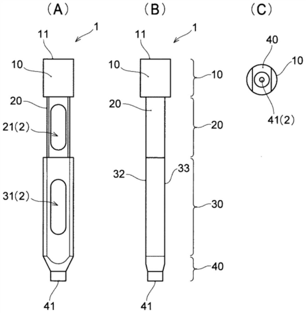
[0034] Hereinafter, the head of the molding material for the 3D molding apparatus according to one embodiment of the present invention will be described with reference to the drawings. figure 1 The head body 1 of the spray head is shown. The head body 1 is formed by cutting, for example, a cylindrical metal rod having a full length of, for example, 32 mm, a diameter of, for example, 4 mmφ, and is made of, for example, 64 titanium (6 mass % mixed with titanium). of aluminum and 4% by mass of vanadium).

[0035]The head body 1 is formed with a channel (through hole) 2 having a diameter of, for example, 2 mmφ, which extends in a straight line from the yarn supply port 11 at one end to the discharge port 41 at the other end where the melted yarn is ejected. In addition, the dimensions of the head body 1 and the channel 2 may be appropriately changed according to the dimensions of the wire.

[0036] The head body 1 is composed of a supply part 10 , a heat insulating part 20 , a ...


PUM

PropertyMeasurementUnit
thermal conductivityaaaaaaaaaa
lengthaaaaaaaaaa
widthaaaaaaaaaa

Abstract

The present invention realizes miniaturization, light weight, energy saving, and long life, and realizes the improvement of the freedom of selection of molding materials by enabling operation at high temperature. Therefore, by making the supply part (10) having the supply port (11) of the wire, the melting part (30) which melts the supplied wire, and the discharge part (40) having the discharge port (41) which discharges the melted wire, , and the thermal insulation part (20) between the supply part (10) and the melting part (30) are integrally formed, even if the melting part is heated to a high temperature, it can effectively suppress the heat transfer from the melting part to the supply part. part, the temperature of the supply part can be kept at an appropriate temperature, and the heat obtained by heating can be efficiently used in the melting part.

Description

technical field [0001] The present invention relates to a nozzle (hot end) of a modeling material for a three-dimensional modeling apparatus (three-dimensional printer). Background technique [0002] In recent years, the use of computers to manufacture three-dimensional shaped objects by three-dimensional printers has become popular. As a head of such a molding material, for example, there are known Image 6 Sprinklers constructed as shown. The nozzle head has a structure in which the nozzle 91 is screwed so that the ejection portion 91a protrudes toward one end side of the heating block 93, the supply portion of the molding material is led out from the other end side of the heating block 93, and the cylindrical portion 92 is screwed into the wire. A shaped molding material (filament 99) is inserted into the cylindrical portion 92, the molding material is heated and melted by the heating block 93, and is ejected from the ejection portion 91a. At this time, a desired amount...

Claims


Application Information

Patent Timeline
Patent Type & Authority Patents(China)
IPC IPC(8): B29C64/209B29C64/118B33Y30/00
CPCB29C64/118B29C64/209B33Y30/00B29C48/05B29C48/02B29C48/30B29C48/802B29C48/865B29C2948/92209B29C2948/9238B29C2948/92409B29C2948/92704B29C2948/92876B29K2071/00
Inventor 谷口秀夫石田畅久
Owner 谷口秀夫
Why Eureka
Try Eureka