Video frequency multiplication method
A frequency doubling and video technology, applied in the field of video frequency doubling, can solve the problems of poor real-time performance, high cost and low flexibility of video frequency doubling, and achieve the effect of reducing the use of logic resources
- Summary
- Abstract
- Description
- Claims
- Application Information
AI Technical Summary
Problems solved by technology
Method used
Image
Examples
Embodiment approach 1
[0025] This embodiment discloses a method for frequency doubling of video, including the following steps:
[0026] Step 1, the video acquisition module collects the original video signal and performs clock domain conversion, and outputs the converted video data to the video frequency multiplication module with a clock of 200MHZ;
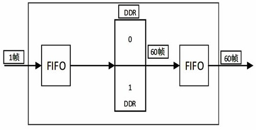
[0027] Step 2, the video frequency doubling module outputs the received video data to the video signal at a frame rate of 60HZ;
[0028] Step 3: The video output module receives the signal output by the video multiplier module, and then converts it into a standard VESA signal for output and display.
[0029] In the above steps, the specific process of step 1 is: FPGA collects the original video signal output by the video receiving chip according to the timing of the VESA standard interface, buffers the original video signal through a FIFO module and performs clock domain conversion, and outputs the data to the video with a 200MHZ clock Multiplier mo...
Embodiment approach 2
[0039] refer to figure 1 As shown, this embodiment discloses a video frequency multiplication method, including: a video acquisition module, a video frequency multiplication module, and a video output module, wherein,
[0040] The parameter configuration module completes the configuration of the HDMI receiver chip, video capture module, video frequency multiplier module, video display module, and HDMI transmitter chip according to the resolution requirements.
[0041] The HDMI receiving chip completes HDMI video reception and converts it into RGB24-bit video signal for FPGA acquisition.
[0042] The video acquisition module completes the acquisition of RGB24-bit data according to the detected video frame line and field synchronization signals.
[0043] The video frequency doubling module receives the image data of the video acquisition module, stores the image data into the memory area by frame, and then outputs the video signal at a fixed 60HZ frame rate.
[0044] The video...
Embodiment approach 3
[0052] On the basis of the solutions disclosed in Embodiments 1 and 2, this embodiment also has a video superimposition module between the video frequency doubling module and the video display module. Specifically, after the multi-channel video frequency doubling modules are respectively scaled by a video infinite zoom module, the video superimposition module completes the superposition according to the superimposition parameters, and the video superposition module sends the superimposed video to the video display module.
[0053] When the video superimposition module superimposes the image data of M channels, according to the configuration parameters of the parameter configuration module and the superposition coordinate points, two frames of image data of different channels are intercepted respectively, and then the current two frames of image data are superimposed.
[0054] Before the two frames of images are superimposed, the video overlay module first obtains the superimpos...
PUM
 Abstract
Description
Claims
Application Information
 - R&D
- Intellectual Property
- Life Sciences
- Materials
- Tech Scout
- Unparalleled Data Quality
- Higher Quality Content
- 60% Fewer Hallucinations
Browse by: Latest US Patents, China's latest patents, Technical Efficacy Thesaurus, Application Domain, Technology Topic, Popular Technical Reports.
© 2025 PatSnap. All rights reserved.Legal|Privacy policy|Modern Slavery Act Transparency Statement|Sitemap|About US| Contact US: help@patsnap.com


