Automobile front suspension framework

A technology for automobiles and sub-frames, which is applied to substructures, vehicle components, jet propulsion devices, etc., and can solve problems such as the inability to accurately control the connection strength between the connecting block and the reinforcing bracket, the inability to ensure the stress conditions of the engine, and the engine's intrusion into the cab, etc. , to achieve the effects of easier quality assurance, good consistency of performance parameters, and controllable safety performance

Active Publication Date: 2020-09-15
ZHEJIANG LIANKONG TECH CO LTD +1
View PDF25 Cites 2 Cited by
  • Summary
  • Abstract
  • Description
  • Claims
  • Application Information

AI Technical Summary

Problems solved by technology

However, since the connection strength between the connection block and the reinforcement bracket depends entirely on the welding strength between the two, and because the welding strength will be affected by the welder, and the influence is large, it is impossible to accurately control the connection block and the reinforcement bracket. The strength of the connection between them, that is, the stress conditions when the engine sinks cannot be guaranteed, resulting in the possibility that the engine cannot be disengaged or may fall off early under a small impact, and every time the engine is disengaged, it will cause damage to the reinforcing bracket and need to be replaced Strengthen the bracket and re-weld the detached structure, the maintenance operation is more cumbersome and the cost is higher
Moreover, in this solution, the engine is partly connected to the side beams of the body and partly connected to the subframe, so that even after the subframe falls off, the engine may still be connected to the side members of the body and cannot fall, resulting in engine intrusion driving. room risk

Method used


Image

  • Automobile front suspension framework
  • Automobile front suspension framework
  • Automobile front suspension framework

Examples


Embodiment 1

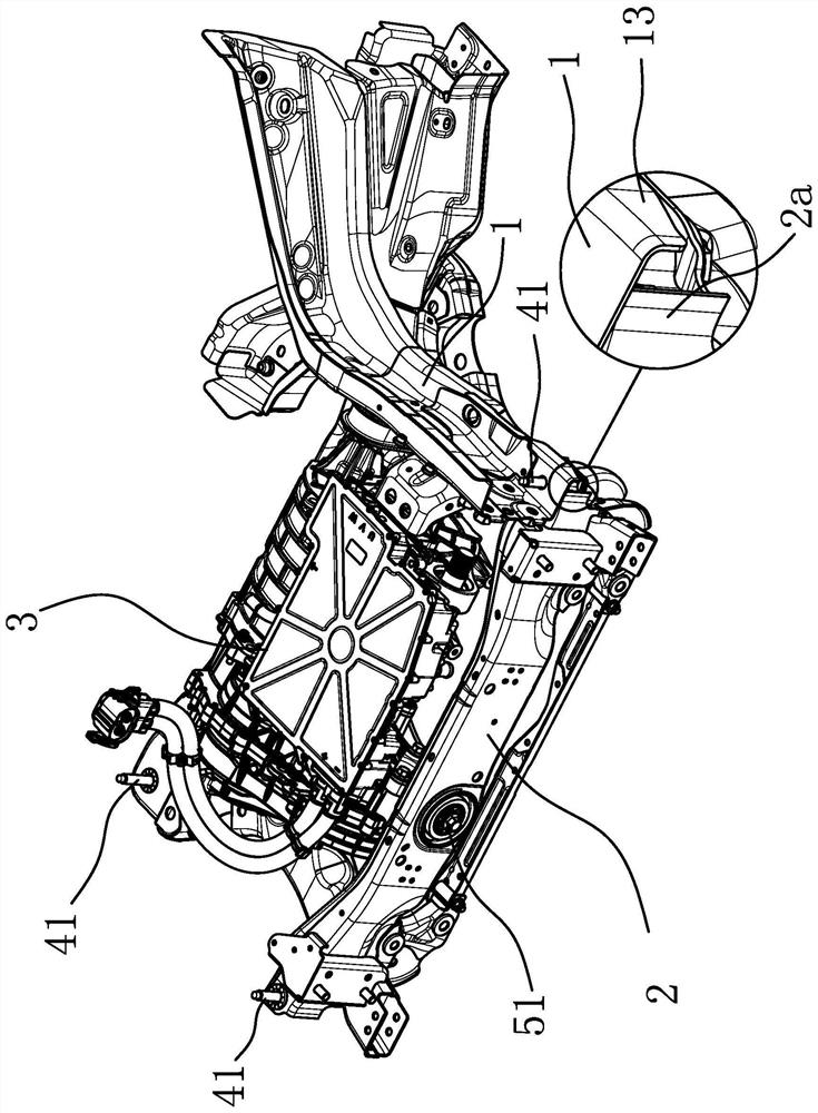
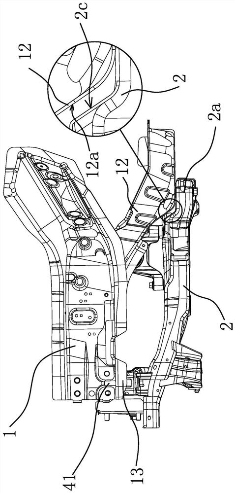
[0038] Such as figure 1 As shown, a kind of automobile front suspension frame, there are two vehicle body longitudinal beams 1 arranged at intervals in the engine compartment in front of the automobile cab, and the front suspension structure includes subframe 2 and power assembly 3, wherein, vehicle body longitudinal beam 1 Both the subframe and the subframe 2 are made of materials with high structural strength and are not easily deformed. The subframe 2 adopts a square frame structure. The powertrain 3 can be an engine or a motor. The suspension structure arranged at three circumferential intervals is connected to the subframe 2, so that the powertrain 3 is only supported by the subframe 2 and forms an integral body with the subframe 2, and the engine is located in the longitudinal direction of the two bodies. Between the beams 1, the subframe 2 is only connected to the two body longitudinal beams 1 through several vertically arranged connecting bolts 41, the material strengt...

Embodiment 2

[0050] The technical solution of this embodiment is basically the same as that of Embodiment 1, the difference is that in this embodiment, the connecting bolt 41 does not use the inner sleeve 42, but the connecting bolt 41 is directly inserted into the mounting hole 2b and Cooperate with the installation hole 2b, of course, when adopting this solution, the material requirements for the suspension part 2a are higher, and the structural strength at the installation hole 2b of the suspension part 2a must be ensured.

Embodiment 3

[0052] Such as Figure 6 As shown, the technical solution of this embodiment is basically the same as that of Embodiment 1. The difference is that in this embodiment, the end of the inner sleeve 42 facing the installation hole 1a and protruding from the end of the installation hole 2b has an annular protrusion. Along 42b, the outer diameter of the annular convex edge 42b is larger than the diameter of the installation hole 2b, which makes the installation and positioning of the inner sleeve 42 more convenient. Moreover, in this embodiment, the screw body is provided with a fracture guide groove 41a along the circumferential direction, and the fracture guide groove 41a is located between the inner sleeve 42 and the screw sleeve 43. In this way, the strength of the screw body where the fracture guide groove 41a is set is relatively lower. Make the screw body easier to break at this place. Of course, the fracture guide groove 41a is not easy to be set too deep, so that the screw...


PUM


Abstract

The invention provides an automobile front suspension framework, belongs to the technical field of automobiles and aims to solve the problems that an existing automobile engine is poor in falling accuracy during collision, inconvenient to maintain in the later period and higher in cost. According to the automobile front suspension framework, two automobile body longitudinal beams which are arranged at intervals are arranged in an engine compartment of an automobile. The front suspension framework comprises an auxiliary frame and a power assembly; the power assembly is connected with the auxiliary frame only through a plurality of suspension structures arranged in the circumferential direction of the power assembly at intervals and is located between the two automobile body longitudinal beams; the auxiliary frame is connected with the two automobile body longitudinal beams only through connecting bolts sequentially penetrating through the auxiliary frame and the automobile body longitudinal beams; the material strength of the auxiliary frame and the material strength of the automobile body longitudinal beams are larger than that of the connecting bolts; and the connecting bolts canbe broken when the auxiliary frame generates longitudinal displacement relative to the automobile body longitudinal beams. When the automobile is subject to collision, an engine and the auxiliary frame sink and fall off, invasion of the engine and the auxiliary frame into a cab is avoided, the accuracy of the breakage of the connecting bolts is higher, and unnecessary breakage is avoided.

Description

technical field [0001] The invention belongs to the technical field of automobiles, and relates to an automobile front suspension structure. Background technique [0002] With the continuous improvement of living standards, the penetration rate of automobiles continues to increase. However, the accident rate of automobiles remains high all the time. Therefore, the safety performance of automobiles has always been an important indicator of automobile performance. Since most of the current automobiles adopt a front-drive structure, the powertrain is usually installed in the engine compartment in front of the cab. When a frontal collision occurs, the rigid engine may be forced to move backwards and squeeze into the cab, causing the driver to The cabin space becomes smaller, causing injury to the driver and passengers. [0003] In order to avoid the above situation, at present, automobile companies have developed engine sinking technology, so that the engine can move downward ...

Claims


Application Information

Patent Timeline
Patent Type & Authority Applications(China)
IPC IPC(8): B62D21/11B62D21/02B60K5/12
CPCB60K5/1208B62D21/02B62D21/11
Inventor 付涛鲁慧才戴强张军然赵治辉
Owner ZHEJIANG LIANKONG TECH CO LTD
Why Eureka
Try Eureka