Lens for infrared temperature measurement
A technology of infrared temperature measurement and lens, which is applied in the field of infrared temperature measurement, can solve the problems of small viewing angle, inability to measure temperature, damage, etc., and achieve the effect of expanding the viewing angle and range of temperature measurement, facilitating installation and disassembly, and expanding the range of temperature measurement
- Summary
- Abstract
- Description
- Claims
- Application Information
AI Technical Summary
Problems solved by technology
Method used
Image
Examples
Embodiment 1
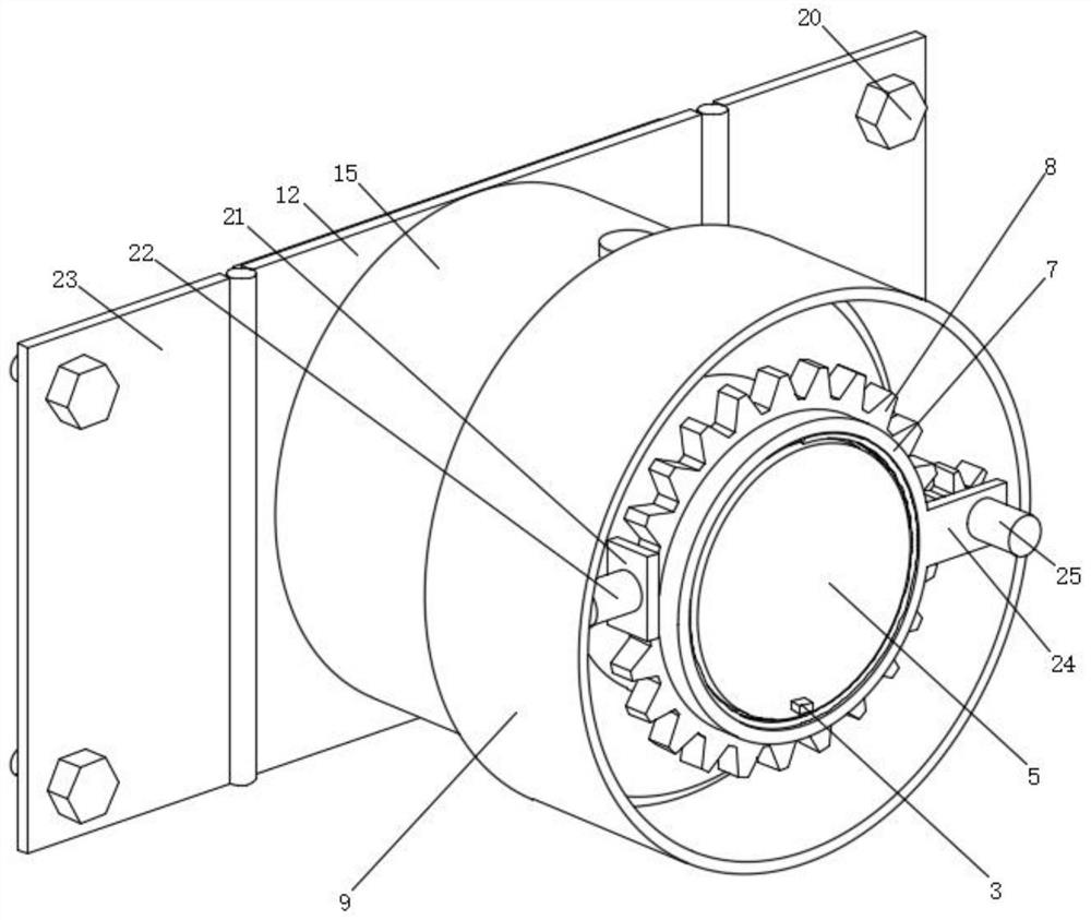
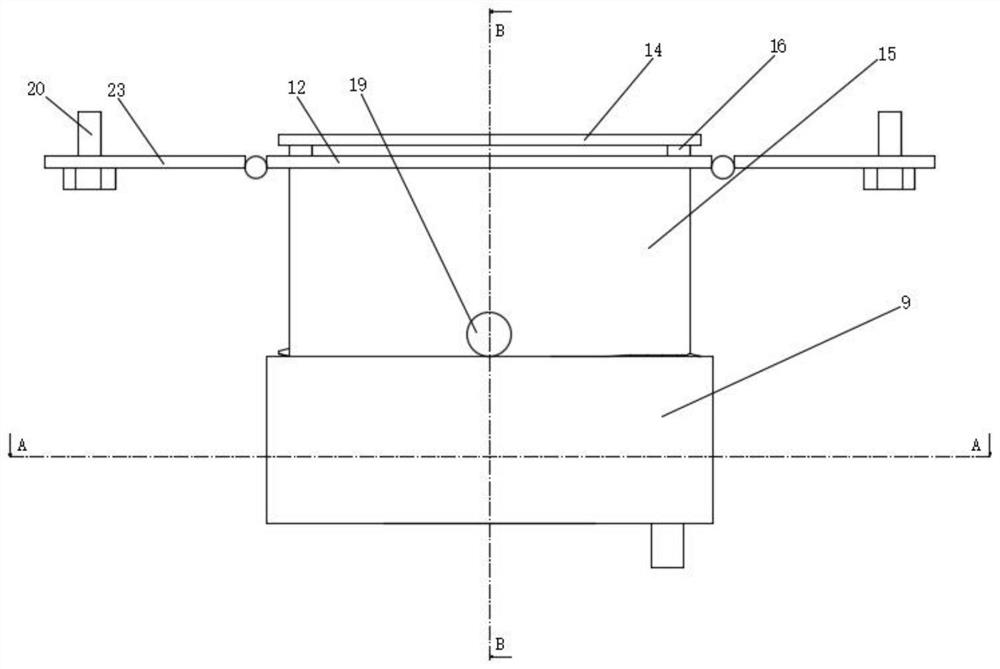
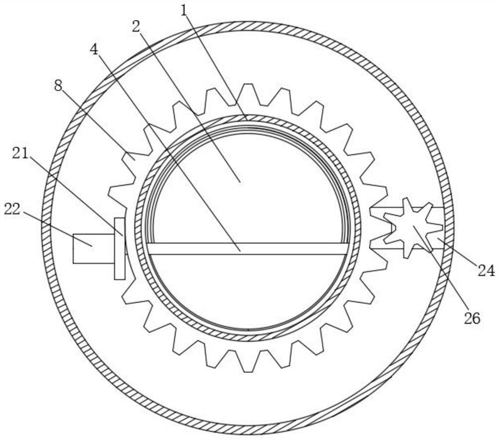
[0026] Embodiment 1: a lens for infrared temperature measurement, including an outer shell 15 and an outer glass cylinder 9;
[0027] Outer shell 15: a wireless transceiver module 27 is fixed on the inner side, and an attached board 10 is fixed inside, and an electric push rod 13 is fixed on the rear side of the attached board 10, and the output end of the electric push rod 13 is fixed through the attached board 10 There is an inner lens body 11, the front side of the outer shell 15 moves through the inner glass tube 1, the front end of the inner lens body 11 moves through the inner glass tube 1, and the front end of the inner glass tube 1 rotates with a driven gear 8, a driven gear 8 An outer attachment plate 21 is fixed on the side of the outer attachment plate 21, and a first motor 22 is fixed on the left side of the outer attachment plate 21. The output end of the first motor 22 passes through the outer attachment plate 21 and is fixed with a transmission rod 4, and the tra...
Embodiment 2
[0031] The difference between this embodiment and Embodiment 1 is:
[0032]In this embodiment, also include base 12, screw 20 and rotating plate 23, the front side of base 12 is fixed on the rear end of outer casing 15, and the left and right ends of base 12 are hinged with rotating plate 23 by hinge, two rotating plates 23 internal threads pass through screws 20, the device can be fixed on the workbench through the base 12, screws 20 and rotating plate 23, and also includes elastic plates 14 and outer pads 16, the outer pads 16 have four and They are respectively fixed on the four corners of the rear side of the base 12, and the rear end of the outer pad 16 is fixed with an elastic plate 14. When the device needs to be fixed on the round surface workbench, the elastic plate 14 can be deformed to fit the round surface to ensure installation The stability of the inner attachment block 18 and the pressing screw 19 are also included. There are two inner attachment blocks 18 and t...
Embodiment 3
[0034] The difference between this embodiment and embodiment two is:
[0035] In this embodiment, an anti-fog film 5 is also included, which is fixed on the front side of the transparent protective cover 6. The anti-fog film 5 is used to prevent the mist from blocking the penetration of infrared rays, and a push block 3 is also included, which is fixed on the transparent protective cover 6. On the front side, it passes through the anti-fog film 5, and the transparent protective cover 6 is conveniently rotated by the push block 3, thereby facilitating the installation and disassembly of the transparent protective cover 6.
[0036] When in use: when the device needs to be installed on a plane, fix the two rotating plates 23 on the plane with screws 20, at this time the elastic plate 14 is close to the plane, when the device needs to be fixed on a circular surface, At this time, the two rotating plates 23 are still fixed on the circular surface by screws 20, but the elastic plate...
PUM
 Abstract
Description
Claims
Application Information
 - R&D Engineer
- R&D Manager
- IP Professional
- Industry Leading Data Capabilities
- Powerful AI technology
- Patent DNA Extraction
Browse by: Latest US Patents, China's latest patents, Technical Efficacy Thesaurus, Application Domain, Technology Topic, Popular Technical Reports.
© 2024 PatSnap. All rights reserved.Legal|Privacy policy|Modern Slavery Act Transparency Statement|Sitemap|About US| Contact US: help@patsnap.com


