Rib type micro-axial force annular two-component strain balance
A technology of strain balance and axial force, which is applied in force/torque/work measuring instruments, power metering, measuring devices, etc., can solve problems such as insufficient accuracy of rotor aerodynamic load measurement results, and achieve simple structure, convenient installation, and small volume. small effect
Inactive Publication Date: 2020-09-11
LOW SPEED AERODYNAMIC INST OF CHINESE AERODYNAMIC RES & DEV CENT
View PDF9 Cites 3 Cited by
- Summary
- Abstract
- Description
- Claims
- Application Information
AI Technical Summary
Problems solved by technology
[0004] However, in the actual test process, the torque balance also transmits part of the rotor pulling force while obtaining the rotor shaft torque, that is, part of t
Method used
View moreImage
Smart ImageViewing Examples
Examples
 PUM
 Abstract
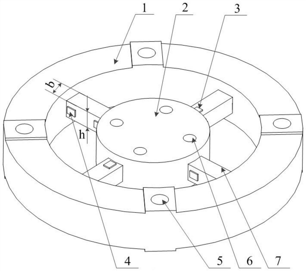
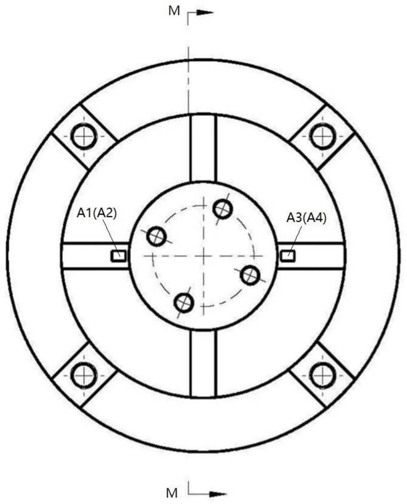
The invention discloses a rib type micro-axial force annular two-component strain balance. The rib type micro-axial force annular two-component strain balance is used for accurately measuring the rotor wing load in a wind tunnel test, is arranged between a rotor wing system and a power system, and is characterized by comprising a fixed end and a floating end which are nested inside and outside, one of the fixed end and the floating end is fixedly connected with the rotor wing system, and the other one of the fixed end and the floating end is fixedly connected with the power system; the fixed end and the floating end are connected through a strain beam, and a torque measuring unit and a tension measuring unit are arranged on the strain beam. The balance can measure the residual tension of the rotor wing while measuring the torque of the rotor wing shaft.
Description
technical field [0001] The invention relates to the technical field of aeronautical dynamometer test measurement, in particular to a rib-type micro-axial force annular two-component strain balance. Background technique [0002] The statements in this section merely provide background information related to the present disclosure and may not necessarily constitute prior art. [0003] Helicopter rotor technology is one of the core technologies of helicopter development, and its test technology is one of the key technologies. In recent years, with the rapid development of various aircraft, the performance requirements for rotors have been continuously improved, and the rotor load measurement test has emerged as the times require. Helicopter rotor tests require real-time measurement of rotor tension, drag, pitching moment, rolling moment, torque and other items. In the helicopter rotor dynamometer test, the traditional force measurement method is to install a rotor balance and...
Claims
Login to View More Application Information
Patent Timeline
 IPC IPC(8): G01M9/06G01M9/04G01L5/00G01L3/10
CPCG01M9/062G01M9/04G01L5/0047G01L3/108
Inventor 黄明其李付华梁勇徐栋霞
Owner LOW SPEED AERODYNAMIC INST OF CHINESE AERODYNAMIC RES & DEV CENT
- R&D Engineer
- R&D Manager
- IP Professional
- Industry Leading Data Capabilities
- Powerful AI technology
- Patent DNA Extraction
Learn More Browse by: Latest US Patents, China's latest patents, Technical Efficacy Thesaurus, Application Domain, Technology Topic, Popular Technical Reports.
© 2024 PatSnap. All rights reserved.Legal|Privacy policy|Modern Slavery Act Transparency Statement|Sitemap|About US| Contact US: help@patsnap.com


