
High-temperature self-starting heat dissipation device for LED lamp

A technology for LED lamps and heat sinks, which is applied in cooling/heating devices of lighting devices, lighting devices, fixed lighting devices, etc. It can solve the problems of affecting the service life of LED lamps, high heat dissipation requirements of LED lamps, and easy heat accumulation. , to avoid abnormal temperature rise, ensure normal operation, and ensure the effect of service life

Inactive Publication Date: 2020-09-11
王明政
View PDF0 Cites 5 Cited by
  • Summary
  • Abstract
  • Description
  • Claims
  • Application Information

AI Technical Summary

Problems solved by technology

[0003] The essence of LED lights is light-emitting diodes. Therefore, when LED light sources are working, except for converting a small part of energy into light energy, most of the energy will be converted into heat energy. Therefore, the heat dissipation requirements of LED lights are generally high, and due to The packaging area of ​​the LED lamp is very small, and it is easy to accumulate heat in it. If the heat is not dissipated in time, the temperature of the electronic components in the LED lamp body will rise abnormally, thereby affecting the service life of the LED lamp body. Therefore, it is necessary to propose a A device capable of cooling and dissipating heat from LED lamps at high temperatures

Method used


Image

  • High-temperature self-starting heat dissipation device for LED lamp
  • High-temperature self-starting heat dissipation device for LED lamp
  • High-temperature self-starting heat dissipation device for LED lamp

Examples


Embodiment 1

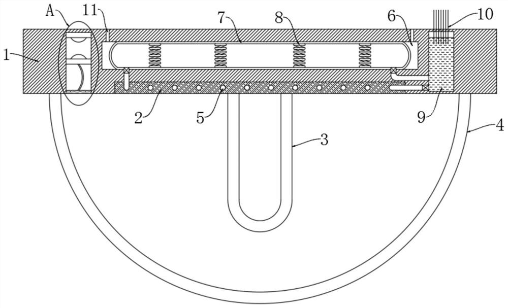
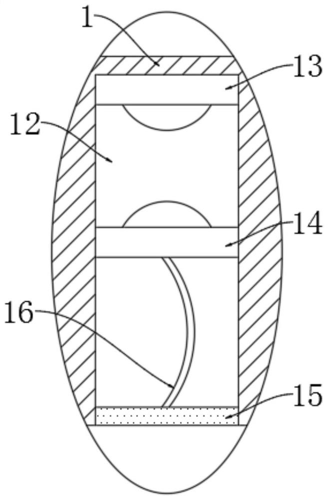
[0019] refer to Figure 1-2 , a high-temperature self-starting heat dissipation device for LED lamps, comprising a lamp holder 1, a heat conduction plate 2 embedded in the lower end of the lamp holder 1, a heat dissipation cavity 5 distributed in a meandering manner is opened in the side wall of the heat conduction plate 2, and the lower end of the heat conduction plate 2 is installed There is a lamp tube 3, a hemispherical lampshade 4 is fixedly arranged at the lower end of the lamp holder 1, the lamp tube 3 is located inside the lamp shade 4, a chute 12 is provided at the lower end of the lamp holder 1, and a heat conducting sheet 15 is embedded in the opening of the chute 12, and the sliding The top of the groove 12 is provided with a first contact piece 13 coupled with the circuit where the lamp tube 3 is located, and a second contact piece 14 is slidably connected between the inner walls of the chute 12, and the second contact piece 14 is fixedly connected to the heat cond...

Embodiment 2

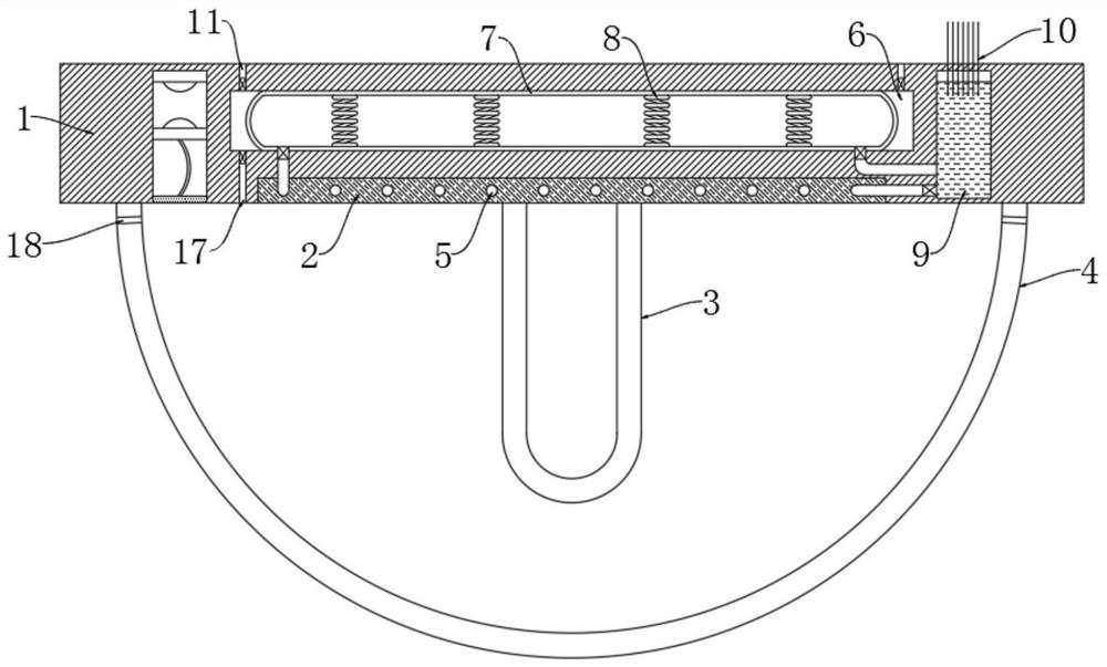
[0027] refer to image 3 , and the embodiment is different in that: a check valve that only allows air to flow from the cavity 6 to the outside is installed in the vent hole 11, and an air outlet 17 is opened at the lower end of the lamp holder 1 at the inner position of the lampshade 4, and the air outlet 17 A one-way valve that only allows air to flow from the inside of the lampshade 4 to the cavity 6 is installed, and a ventilation hole 18 is opened on the side wall of the lampshade 4 .

[0028] In this embodiment, the spring 8 is energized and shakes, thereby driving the elastic airbag 7 to continuously shrink and recover. When the elastic airbag 7 shrinks, the space in the cavity 6 becomes larger, the air pressure decreases, and the hot air inside the lampshade 4 enters from the air outlet 17. In the cavity 6, when the elastic airbag 7 recovers, the space in the cavity 6 decreases, the air pressure increases, and the hot air is extruded to the outside through the vent hol...


PUM


Abstract

The invention discloses a high-temperature self-starting heat dissipation device for an LED lamp. The device comprises a lamp holder, a heat conduction plate is embedded in the lower end of the lamp holder; a heat dissipation cavity in zigzag distribution is formed in the side wall of the heat conduction plate; a lamp tube is installed at the lower end of the heat conduction plate, a hemisphericallampshade is fixedly arranged at the lower end of the lamp holder, the lamp tube is located in the lampshade, a sliding groove is formed in the lower end of the lamp holder, a heat conduction piece is embedded in an opening of the sliding groove, and a first power connection piece coupled with a circuit where the lamp tube is located is arranged at the top in the sliding groove. The first power connection piece, a second power connection piece, a memory alloy, a liquid pumping mechanism, an air outlet hole and the like are arranged; according to the LED lamp, the pulse current can be suppliedto a spring to drive the cooling liquid to circularly flow when an LED and the like are at abnormally high temperature, so that heat accumulated in the lampshade is taken away, the exchange speed ofair in the lampshade and outside air can be increased, the auxiliary heat dissipation effect is achieved, and the normal operation and the service life of the LED lamp body are effectively guaranteed.

Description

technical field [0001] The invention relates to the field of LEDs, in particular to a high-temperature self-starting cooling device for LED lamps. Background technique [0002] Due to its superior energy saving, environmental protection, high efficiency, safety, stable service life, high color rendering index and fast response, LED lights have replaced traditional incandescent lamps and become an indispensable and important part of urban lighting. The development and construction of urban civilization is of great significance. [0003] The essence of LED lights is light-emitting diodes. Therefore, when LED light sources are working, except for converting a small part of energy into light energy, most of the energy will be converted into heat energy. Therefore, the heat dissipation requirements of LED lights are generally high, and due to The packaging area of ​​the LED lamp is very small, and it is easy to generate heat accumulation in it. If the heat is not dissipated in t...

Claims


Application Information

Patent Timeline
Patent Type & Authority Applications(China)
IPC IPC(8): F21S8/00F21V19/00F21V23/06F21V29/503F21V29/57F21V29/61F21V29/76F21V29/83F21Y115/10
CPCF21S8/00F21V19/001F21V23/06F21V29/503F21V29/57F21V29/61F21V29/76F21V29/83F21Y2115/10
Inventor 王明政付小丽
Owner 王明政
Learn More