Eureka AIR delivers breakthrough ideas for toughest innovation challenges, trusted by R&D personnel around the world.

Clothing fabric sewing cutting equipment

A fabric and sewing technology, which is applied in the field of clothing fabric sewing and cutting equipment, can solve the problems of low cutting efficiency, frequent disassembly and assembly, and poor pressing effect, and achieve the effect of simple structure, improved cutting efficiency, and avoiding replacement

Inactive Publication Date: 2020-09-11
王涛
View PDF0 Cites 0 Cited by
  • Summary
  • Abstract
  • Description
  • Claims
  • Application Information

AI Technical Summary

Problems solved by technology

[0002] There are many shortcomings in the existing sewing and cutting equipment for clothing fabrics. First, because the cutting process of clothing fabrics has low precision, and the cutting process involves the tension of the fabrics, the fabrics can be shortened efficiently. , the existing equipment has a poor effect on fabric compression, and during the operation of the equipment, due to the poor compression effect, the cutting efficiency of the equipment for the fabric is low, so that the quality of the fabric processed is low, and When cutting the fabric continuously, since the continuous cutting requires a high degree of sharpness of the blade, it is often used to disassemble the cutting knife, and then fully grind the cutting knife to keep it sharp. At this time, due to frequent disassembly and assembly, the continuous processing capacity of the equipment is reduced

Method used


Image

  • Clothing fabric sewing cutting equipment
  • Clothing fabric sewing cutting equipment
  • Clothing fabric sewing cutting equipment

Examples


Embodiment Construction

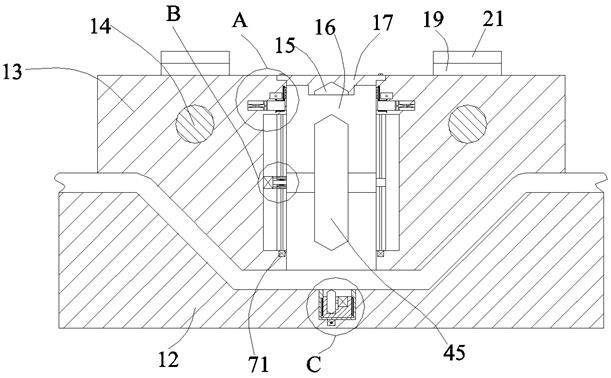
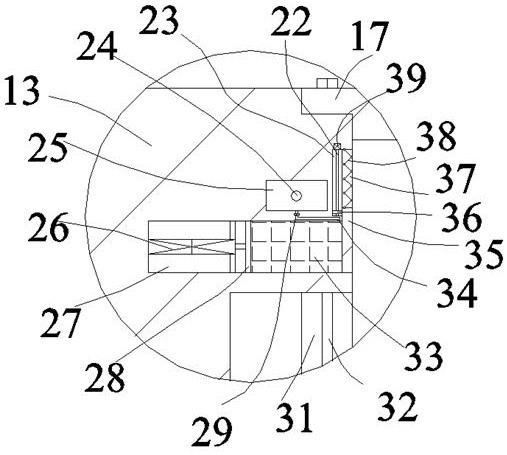
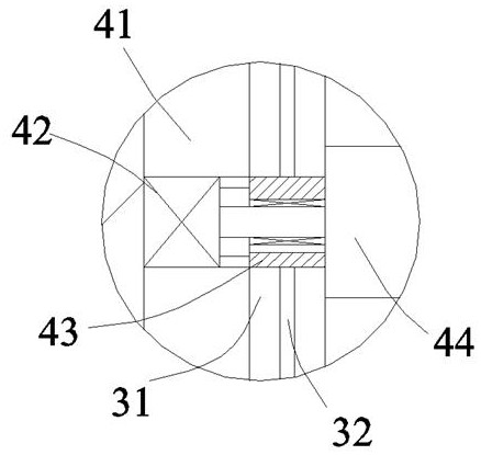
[0024] Such as Figure 1-Figure 4 As shown, the present invention will be described in detail. For the convenience of description, the orientations mentioned below are now specified as follows: figure 1 The projection relationship is the same in the up, down, left, and right directions. The garment fabric sewing and cutting equipment of the present invention includes a bottom seat body 12, and a symmetrical support frame 21 is fixed on the top of the bottom seat body 12. There is an inner cavity 19 with an opening. A motor-driven sliding rod 14 is rotatably arranged between the cavities 19. The outer surface of the sliding rod 14 is screwed and connected with a sliding block 13, and the sliding block 13 is provided An open through cavity 16 is provided with a cutting and grinding device that has a lifting function to cut the fabric and has a certain grinding effect. The through cavity 16 is provided on the lower side of the A lower cutting device in the bottom seat 12 and used ...


PUM


Abstract

The invention discloses clothing fabric sewing cutting equipment. The clothing fabric sewing cutting equipment comprises a bottom base body, wherein the top of the bottom base body is fixedly providedwith supporting frames which are symmetrical; inner cavities with an openings are arranged in the supporting frames; a slide rod driven by a motor is rotatably arranged between the inner cavities; the outer surface of the slide rod is in threaded fitted connection to a slide block; a penetrating inner cavity with an opening is arranged in the slide block; a cutting grinding device which has a lifting function for cutting the fabric and has certain grinding effect is arranged in the penetrating inner cavity; and the lower side of the penetrating inner cavity is provided with a lower cutting device, which is positioned in the bottom base body and is used for cutting off the fabric from the lower part to the upper part. The equipment adopts a movable pressing way, and can sufficiently grindbefore a cutter cuts; and grinded blades can be utilized to press and cut off the fabric, so that cutting efficiency and equipment use reliability are greatly improved, and therefore, the cutter is prevented from being dismounted to replace.

Description

Technical field [0001] The invention relates to the technical field of sewing equipment, in particular to a clothing fabric sewing and cutting equipment. Background technique [0002] The existing garment fabric sewing and cutting equipment has many shortcomings. First of all, because the cutting process of the garment fabric is less accurate, and the tensioning effect on the fabric is involved in the cutting process, the fabric can be cut efficiently. , The existing equipment has a poor effect on fabric compaction, and during the operation of the equipment, due to the poor compaction effect, the equipment has low cutting efficiency for the fabric, resulting in low quality of the fabric processed. When the fabric is continuously cut, because the continuous cutting requires a high degree of sharpness of the blade, at this time, the cutting knife is often removed, and then the cutting knife is fully ground to keep it sharp. At this time, due to frequent disassembly and assembly, t...

Claims


Application Information

Patent Timeline
IPC IPC(8): D05B37/04B24B3/46
CPCB24B3/46D05B37/04
Inventor 王涛
Owner 王涛
Why Eureka
Eureka Blog
Learn More