
Automatic feeding machine for round bar parts

An automatic feeding and parts technology, applied in the direction of conveyors, conveyor objects, transportation and packaging, etc., can solve the problems of insufficient product surface protection, short transmission path, large vibration, etc. The effect of small area and stable feeding

Active Publication Date: 2020-09-11
聚鼎科技(苏州)有限公司
View PDF7 Cites 3 Cited by
  • Summary
  • Abstract
  • Description
  • Claims
  • Application Information

AI Technical Summary

Problems solved by technology

The advantage of step feeding is that it has high stability, but the size is large and the transmission path is long; the advantage of jacking feeding is that the volume is small and the transmission path is short, but the stability is not high, and the interference between round bars is large. The product keeps falling, and the protection of the product surface is insufficient; the main working area of ​​screening and feeding is on the screening plate, and the posture of the product placed after the screening plate vibrates changes, and the posture that meets the requirements flows out of the sieve body, and the material is loaded by the feeding mechanism, which is generally suitable for small Screening and discharging of large pieces; of course, it can also be done for large pieces, but large-scale screening, vibration, noise, and space are also the largest, and an independent workshop must be set up for operations

Method used


Image

  • Automatic feeding machine for round bar parts
  • Automatic feeding machine for round bar parts
  • Automatic feeding machine for round bar parts

Examples


Embodiment Construction

[0020] The following will clearly and completely describe the technical solutions in the embodiments of the present invention with reference to the accompanying drawings in the embodiments of the present invention. Obviously, the described embodiments are only some, not all, embodiments of the present invention. Based on the embodiments of the present invention, all other embodiments obtained by persons of ordinary skill in the art without making creative efforts belong to the protection scope of the present invention.

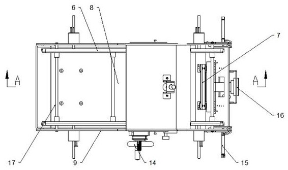
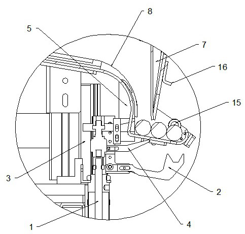
[0021] see Figure 1~4 , in an embodiment of the present invention, an automatic feeding machine for round bar parts, comprising a monolithic lower bracket 12, the lower side of the monolithic lower bracket 12 is threaded with several mechanism feet 13, and the mechanism feet 13 It is distributed in a rectangular shape and the lower side of the mechanism anchor 13 is fixed with a rubber pad, and the lower side of the rubber pad is fixed with a gasket to increa...


PUM


Abstract

The invention discloses an automatic feeding machine for round bar parts. The automatic feeding machine comprises a material arranging lower support, the lower side of the material arranging lower support is connected with a plurality of mechanism ground feet through threads, the mechanism ground feet are distributed in a rectangular shape, rubber pads are fixed to the lower sides of the mechanismground feet, and gaskets are fixed to the lower sides of the rubber pads and used for increasing the supporting area and improving the stability; and a material frame supporting foot is fixed to theleft end of the upper side of the material arranging lower support, a material frame is fixed to the upper side of the material frame supporting foot, and the material frame comprises an outer material frame support and a bottom plate. The automatic feeding machine completely completes the bar feeding action and is small in occupied area, stable in feeding and small in product action range, and thus the automatic feeding machine is an efficient operation mechanism for feeding machining of bar parts; and a pure mechanism is adopted to act, so that the products are located at different regular positions in different time periods on one movement path, and stable feeding of the products is achieved.

Description

technical field [0001] The invention relates to the technical field of feeding round bar parts, in particular to an automatic feeding machine for round bar parts. Background technique [0002] The round bar is the main raw material of the shaft parts. After the design of the shaft parts is completed, a variety of processing is carried out on the round bar, such as outer circle processing, milling, slotting, etc., so as to meet the design requirements. When the existing round bar is slotting , mostly through manual material distribution, feeding, positioning, and its work efficiency is low. [0003] The traditional round bar feeding machine can be divided into several types: step feeding, jacking feeding, and vibrating screening feeding. The advantage of step feeding is that it has high stability, but the size is large and the transmission path is long; the advantage of jacking feeding is that the volume is small and the transmission path is short, but the stability is not h...

Claims


Application Information

Patent Timeline
IPC IPC(8): B65G47/14B65G47/91
CPCB65G47/1421B65G47/915B65G2201/0217
Inventor 张崇峻孙山郁金德
Owner 聚鼎科技(苏州)有限公司
Learn More