Jointed connecting link mechanism with linkage between moving side mold and bottom mold of bottle blowing machine

A connecting rod mechanism and side mold technology, applied in the field of combined connecting rod mechanism, can solve the problems of difficult cam installation and positioning, high machining accuracy requirements, and easy wear of the cam profile, so as to enhance the stability and reliability of motion, reduce the Vibration and shock, the effect of improving high-speed performance

Pending Publication Date: 2020-09-11
JIANGSU NEWAMSTAR PACKAGING MACHINERY
View PDF0 Cites 1 Cited by
  • Summary
  • Abstract
  • Description
  • Claims
  • Application Information

AI Technical Summary

Problems solved by technology

Disadvantages: 1) The design and machining accuracy of the cam flange or groove profile of the cylindrical space cam is high, the installation and positioning of the cam is difficult, and the rotor is easily stuck; 2) The contact surface between the rotor and the cam profile is easy to form point contact, and the pressure The stress is large, the rotor is easily damaged or the cam surface is easy to wear; 3) Due to the limitation of the space size, the pressure angle of the cam is usually too large. Similarly, the rotor is easily damaged or the cam surface is easy to wear

Method used


Image

  • Jointed connecting link mechanism with linkage between moving side mold and bottom mold of bottle blowing machine
  • Jointed connecting link mechanism with linkage between moving side mold and bottom mold of bottle blowing machine
  • Jointed connecting link mechanism with linkage between moving side mold and bottom mold of bottle blowing machine

Examples


Embodiment Construction

[0028] The technical solution of the present invention will be further described below in conjunction with the accompanying drawings.

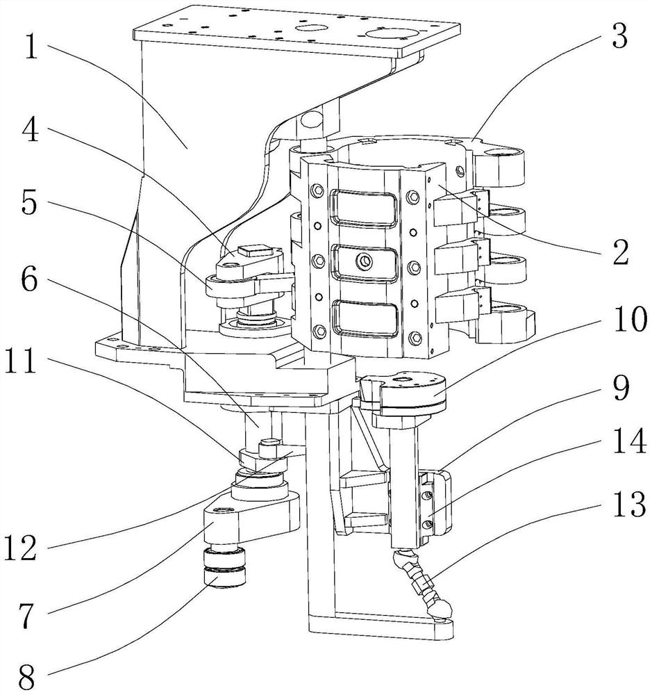
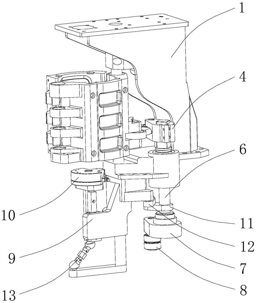
[0029] see Figure 1-2 As shown, the above-mentioned combined linkage mechanism of the blowing motorized side mold and the bottom mold includes a mold frame bracket 1, a fixed side mold 2, a moving side mold 3, a side mold swing arm 4, a side mold connecting rod 5, a side mold Die swing shaft 6, side mold rotor arm 7, side mold cam rotor 8, bottom mold support 9, bottom mold 10, bottom mold swing arm 11, bottom mold connecting rod 12, space connecting rod 13 and bottom mold guide rail 14. The movable side mold 3 can be rotated around the direction of the first axis and is installed on the mold frame bracket 1, the fixed side mold 2 is fixed on the mold frame bracket 1, and the movable side mold 3 rotates close to or away from the fixed side mold 2, Mold opening and closing for mutual cooperation.

[0030] Among the bottom mold 10, the movabl...


PUM


Abstract

The invention discloses a jointed connecting link mechanism with linkage between a moving side mold and a bottom mold of a bottle blowing machine. A side mold rotor arm which drives the side mold to carry out separation and reunion motion synchronously drives the bottom mold to carry out deflection lifting motion while drives the moving side mold to carry out separation and reunion motion, the separation and reunion motion of the moving side mold can be in accurate cooperation with deflection lifting motion of the bottom mold, and then it is implemented that the deflection lifting motion of the bottom mold can be in effective synergy with the separation and reunion motion of the moving side mold. According to the jointed connecting link mechanism with linkage between the moving side mold and the bottom mold of the bottle blowing machine, after a first plane four-bar linkage is connected with a space dual-swing slider mechanism in series, and then a formed tandem type combined connecting rod type bottom mold deflection lifting mechanism is combined with a second plane four-bar linkage. Parts are connected with one another through sliding pairs or revolute pairs or spherical pairs. The jointed connecting link mechanism with linkage between the moving side mold and the bottom mold of the bottle blowing machine is simple and low in live load; and the vibration and impact of the mechanism can be effectively reduced, abrasion of the parts is reduced, the motion of the bottom mold can be accurately controlled, the bottle blowing machine is improved in motion stability and reliability, and the high-speed performance of the whole machine is improved.

Description

technical field [0001] The invention relates to the technical field of bottle blowing machines, in particular to a combined linkage mechanism in which a side mold and a bottom mold of a bottle blowing motor are linked. Background technique [0002] The bottle blowing machine is the key equipment for producing plastic bottles for various liquid packaging (filling). Each process of the bottle blowing machine has strict requirements and high requirements for mutual cooperation, especially for the synchronous control of the opening and closing movement of the single-side opening and closing side mold and the deflection and lifting movement of the bottom mold. [0003] The existing mechanism for realizing the synchronous movement of the bottom mold and the movable side mold is generally a composite mechanism formed by a cylindrical space cam and a space linkage mechanism. The space linkage mechanism realizes the deflection of the bottom mold, and the deflected bottom mold is in t...

Claims


Application Information

Patent Timeline
Patent Type & Authority Applications(China)
IPC IPC(8): B29C49/56
CPCB29C49/56
Inventor 董腾中张晓飞吴书朋刘丁丁于荣鹏
Owner JIANGSU NEWAMSTAR PACKAGING MACHINERY
Why Eureka
Try Eureka