Current waveform control system and method for digital pulse power supply of ion synchrotron

A synchrotron, digital pulse technology, used in pulse shaping, automatic power control, electrical components, etc., can solve the problem of waveform data transmission reliability power supply controller waveform storage, current waveform control method can not meet the requirements, can not describe the rise It can improve the flexibility and reliability, improve the calculation speed, and increase the synchronization effect.

Active Publication Date: 2020-09-08
INST OF MODERN PHYSICS CHINESE ACADEMY OF SCI
View PDF9 Cites 5 Cited by
  • Summary
  • Abstract
  • Description
  • Claims
  • Application Information

AI Technical Summary

Problems solved by technology

[0004] However, for the BUMP (convex rail) power supply, in order to ensure the control accuracy of the current rising process, the voltage of the front-stage busbar has a charging process before the output waveform, so the front-stage charging needs real-time control. The above-mentioned current waveform control The method does not meet the requirements
In addition, the rise time of the current is generally less than 5ms, and the interval of 2ms for the waveform data obviously cannot describe the current curve of the rise section.
However, if a smaller interval is directly used, such as 10us, although the time accuracy of the current rise can be guaranteed, due to the long flat-top current time, a large amount of data will be generated in the flat-top current waveform, which will make the waveform data transmission reliable. Waveform storage for power and power controllers presents serious problems

Method used


Image

  • Current waveform control system and method for digital pulse power supply of ion synchrotron
  • Current waveform control system and method for digital pulse power supply of ion synchrotron
  • Current waveform control system and method for digital pulse power supply of ion synchrotron

Examples


Embodiment Construction

[0025] The present invention will be described in detail below in conjunction with the accompanying drawings. However, it should be understood that the accompanying drawings are provided only for better understanding of the present invention, and they should not be construed as limiting the present invention.

[0026] Since the current waveform control system and method of the ion synchrotron digital pulse power supply proposed by the present invention involve the related content of extracting the BUMP power supply, the relevant content will be introduced below so that those skilled in the art can understand the content of the present invention more clearly.

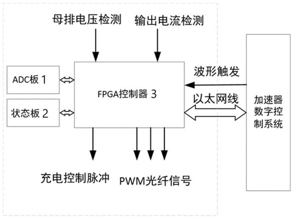
[0027] The lead-out BUMP magnet is an inductive load. To precisely control the rise time of its excitation current and the stability of the platform current requires precise control of the busbar voltage of the power supply. Due to factors such as the dispersion of circuit parameters, the busbar voltage of the power supp...


PUM


Abstract

The invention relates to a current waveform control system and method for a digital pulse power supply of an ion synchrotron. The system is characterized in that the current waveform control system comprises an ADC board, a state board, and an FPGA controller; the ADC board is used for acquiring a current signal and a busbar voltage signal of a digital pulse power supply in the ion synchrotron inreal time; the state board is used for determining the running state of the digital pulse power supply and controlling the startup, shutdown or reset of the current waveform control system; the FPGA controller is used for calculating an output current value point by point in real time according to an output waveform trigger case sent by the control system in the ion synchrotron and a plurality ofcurrent waveform data generated by an upper computer, converting the output current value into a PWM signal and sending the PWM signal to a main circuit driver of the digital pulse power supply; and real-time charging and discharging control is carried out on the busbar voltage of the digital pulse power supply according to the busbar voltage signal acquired by the ADC board, therefore the currentwaveform control system and method can be widely applied to the field of ion accelerators.

Description

technical field [0001] The invention relates to a current waveform control system and method for a digital pulse power supply of an ion synchrotron, belonging to the field of ion accelerators. Background technique [0002] The ion synchrotron is a circular acceleration device that uses a high-frequency electric field to accelerate ions on a certain circular orbit. The strength of the magnetic field in the ion synchrotron increases with the increase of the energy of the accelerated ions, thereby maintaining the ion cyclotron frequency and the high-frequency accelerator electric field. Synchronize. The ion synchrotron requires the magnetic field generated to be constant or to change according to the required law. The excitation power supply generates a magnetic field by supplying current to the magnet. It is usually divided into a steady-current power supply and a pulse power supply. The steady-current power supply produces a constant magnetic field, and the pulse power suppl...

Claims


Application Information

Patent Timeline
Patent Type & Authority Applications(China)
IPC IPC(8): H05H7/02H03L5/00H03K5/04
CPCH03K5/04H03L5/00H05H7/02H05H2007/022
Inventor 赵江周忠祖高大庆张华剑冯秀明
Owner INST OF MODERN PHYSICS CHINESE ACADEMY OF SCI
Why Eureka
Try Eureka