
Continuous wave radar front end

A wave radar and front-end technology, applied in the field of continuous wave radar front-end, can solve the problems of large volume and poor stability

Active Publication Date: 2020-09-08
BEIJING JULI SCI & TECH
View PDF3 Cites 1 Cited by
  • Summary
  • Abstract
  • Description
  • Claims
  • Application Information

AI Technical Summary

Problems solved by technology

[0005] The embodiment of the present invention provides a continuous wave radar front end to solve the problems of poor stability and large volume of the existing continuous wave radar front end

Method used


Image

  • Continuous wave radar front end
  • Continuous wave radar front end

Examples


Embodiment Construction

[0028] In order to make the purpose, technical solutions and advantages of the embodiments of the present invention clearer, the technical solutions in the embodiments of the present invention will be clearly and completely described below in conjunction with the drawings in the embodiments of the present invention. Obviously, the described embodiments It is a part of embodiments of the present invention, but not all embodiments. Based on the embodiments of the present invention, all other embodiments obtained by persons of ordinary skill in the art without creative efforts fall within the protection scope of the present invention.

[0029] The terms "first", "second", "third", "fourth", etc. (if any) in the description and claims of the present invention and the above drawings are used to distinguish similar objects and not necessarily Describe a specific order or sequence. It is to be understood that the data so used are interchangeable under appropriate circumstances such ...


PUM


Abstract

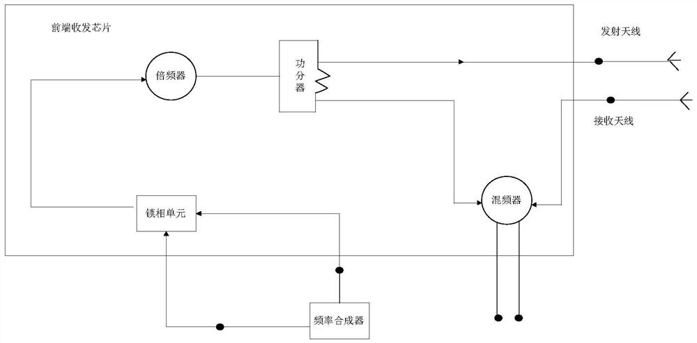
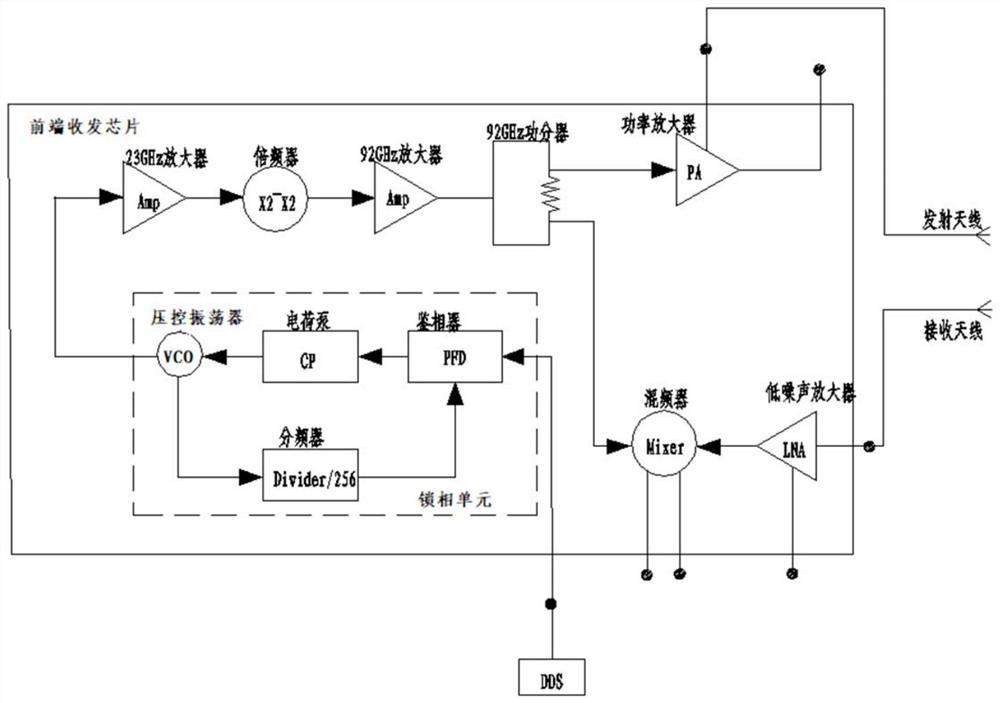
The embodiment of the invention provides a continuous wave radar front end, which comprises a frequency synthesizer, a front end transceiver chip, a transmitting antenna and a receiving antenna, and is characterized in that the front end transceiver chip comprises a phase locking unit, a frequency multiplier, a power divider and a frequency mixer; the frequency synthesizer generates a swept-frequency signal and outputs the swept-frequency signal to the phase locking unit; the phase locking unit performs phase locking according to the swept-frequency signal; a signal is output to the frequencymultiplier; the frequency multiplier performs frequency multiplication processing on the signal; a signal is output to the power divider; the power divider divides the signal into two paths; wherein one path is sent to the transmitting antenna, the other path is sent to the frequency mixer, the frequency mixer mixes the other path of signals output by the power divider and the signals received bythe receiving antenna and outputs the signals to the signal processor to extract radar target information, the problems that an existing continuous wave radar is poor in front-end stability and largein size are solved, and the requirements of various application scenes are met.

Description

technical field [0001] Embodiments of the present invention relate to the technical field of radar, in particular to a continuous wave radar front end. Background technique [0002] The basic theory of radar originated in the 1880s. On the basis of the electromagnetic principle published by Maxwell, the famous German physicist Heinrich Hertz proved by experiments that electromagnetic waves can be reflected by metal objects and successfully received the reflected echo. Radar is an electromagnetic system used to detect and locate target objects. Its basic working principle is to send a special waveform, such as a pulse-modulated sine wave, and then receive the reflected waveform and analyze and detect the echo signal. [0003] Radar is used extensively at sea, on land, in the air and in outer space. Radar on land is mainly used to detect, locate and track land or low-altitude targets, etc. Radar is widely used and has many types, and its classification method is therefore mor...

Claims


Application Information

Patent Timeline
IPC IPC(8): G01S13/02
CPCG01S13/02Y02A90/10
Inventor 桂杰蔡隽
Owner BEIJING JULI SCI & TECH
Learn More