


Quick Research
Generate reliable direction feasibility study reports for your R&D in just a few steps.

Technical Q&A
Discover and master advanced knowledge NOW. Basics, ideas, possibilities, all at once.

Find Solutions
As an expert in R&D theories, this can generate solutions to your technical problems instantly.

Evaluate Feasibility
Analyze your overall solution with one click, know your potential R&D risks in advance.

Monitor Landscape
Get weekly tech updates, stay abreast of the latest tech innovations and key insights.
Mechanical locking device suitable for pipeline
A locking device and mechanical technology, applied in the direction of mechanical equipment, locking fasteners, threaded fasteners, etc., can solve the problems of loosening and loosening of threaded pipe connections, and achieve the purpose of preventing loosening, simple structure and practicality. good effect
- Summary
- Abstract
- Description
- Claims
- Application Information
AI Technical Summary
Problems solved by technology
Method used
Image

Examples
Embodiment 1
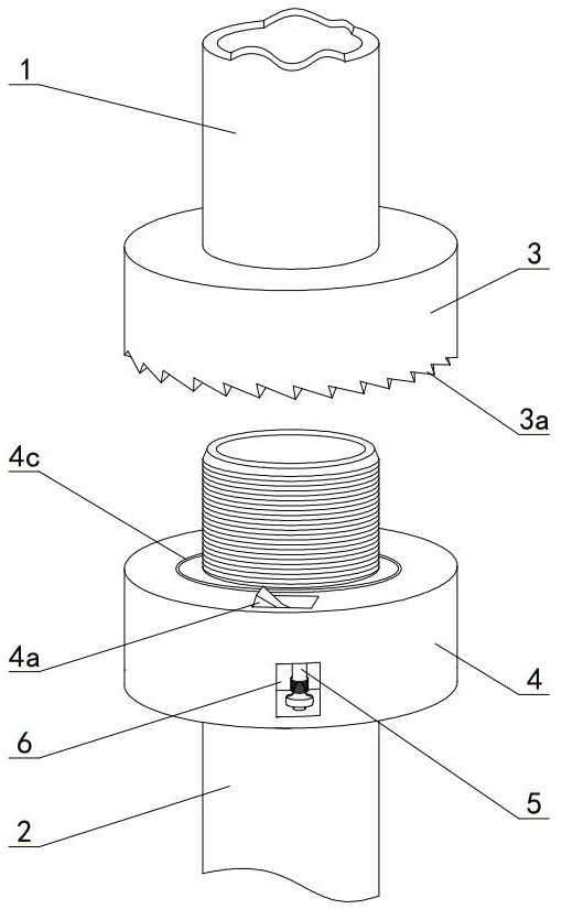
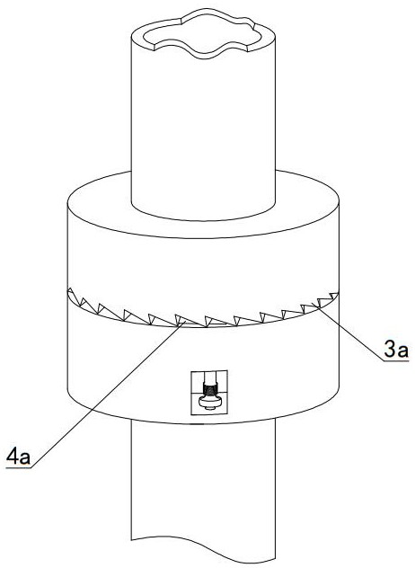
[0039] Such as Figure 1-4 As shown, a mechanical locking device suitable for pipelines includes a stop ring male part 3 sleeved on one end of the female threaded pipe 1 and a stop ring female part 4 sleeved on the outer threaded pipe 2. The bottom surface of the male part 3 of the movable ring is uniformly distributed with ratchet teeth 3a, and the female part 4 of the stop ring is movably connected with a pawl 4a for cooperating with the ratchet teeth 3a. The internal thread pipe 1 and the external thread pipe 2 are screwed together. , The ratchet tooth 3a can be made to abut against the stop ring female part 4, and the pawl 4a can be clamped between any two ratchet teeth 3a, so that the stop ring male part 3 can only be opposite to the stop ring female part 4 To rotate (rotate in the tightening direction), the stop ring female member 4 is provided with a reset mechanism for pushing the pawl 4a to withdraw the pawl 4a from between the ratchet teeth 3a.
[0040] When the mechani...
Embodiment 2
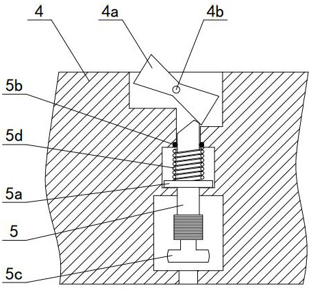
[0048] Such as Figure 7-11 As shown, the difference between this embodiment and Embodiment 1 is only in the structure of the reset mechanism. Specifically, a through hole is formed on the stop ring female member 4 along the axial direction, and the reset mechanism includes a through hole. The stop pin 7 can move up and down. The top end of the stop pin 7 is wedge-shaped and can extend upward from the mounting hole to form the pawl 4a. The bottom end of the stop pin 7 is provided with a female stop ring On the convex block 5c on the bottom end of the part 4, the inner wall surface of the through hole is provided with an upper step surface and a lower step surface. The outer wall of the stop pin 7 is fixedly connected with a limit ring 5a that can abut the upper and lower step surfaces. The limit ring 5a and A compression spring 5d is connected between the lower step surfaces, a sealing ring 5b is clamped on the inner wall surface of the through hole, and the stop pin 7 is pulle...
PUM
 Abstract
Description
Claims
Application Information
 - R&D Engineer
- R&D Manager
- IP Professional
- Industry Leading Data Capabilities
- Powerful AI technology
- Patent DNA Extraction
Browse by: Latest US Patents, China's latest patents, Technical Efficacy Thesaurus, Application Domain, Technology Topic, Popular Technical Reports.
© 2024 PatSnap. All rights reserved.Legal|Privacy policy|Modern Slavery Act Transparency Statement|Sitemap|About US| Contact US: help@patsnap.com