


Quick Research
Generate reliable direction feasibility study reports for your R&D in just a few steps.

Technical Q&A
Discover and master advanced knowledge NOW. Basics, ideas, possibilities, all at once.

Find Solutions
As an expert in R&D theories, this can generate solutions to your technical problems instantly.

Evaluate Feasibility
Analyze your overall solution with one click, know your potential R&D risks in advance.

Monitor Landscape
Get weekly tech updates, stay abreast of the latest tech innovations and key insights.
Puncture forceps and use method thereof
A technology of forceps rod and forceps body, applied in the field of puncture forceps, which can solve the problems of tissue pulling and tissue damage, and achieve the effects of small wounds, reduced operation costs, and fast recovery
- Summary
- Abstract
- Description
- Claims
- Application Information
AI Technical Summary
Problems solved by technology
Method used
Image

Examples
Embodiment 1
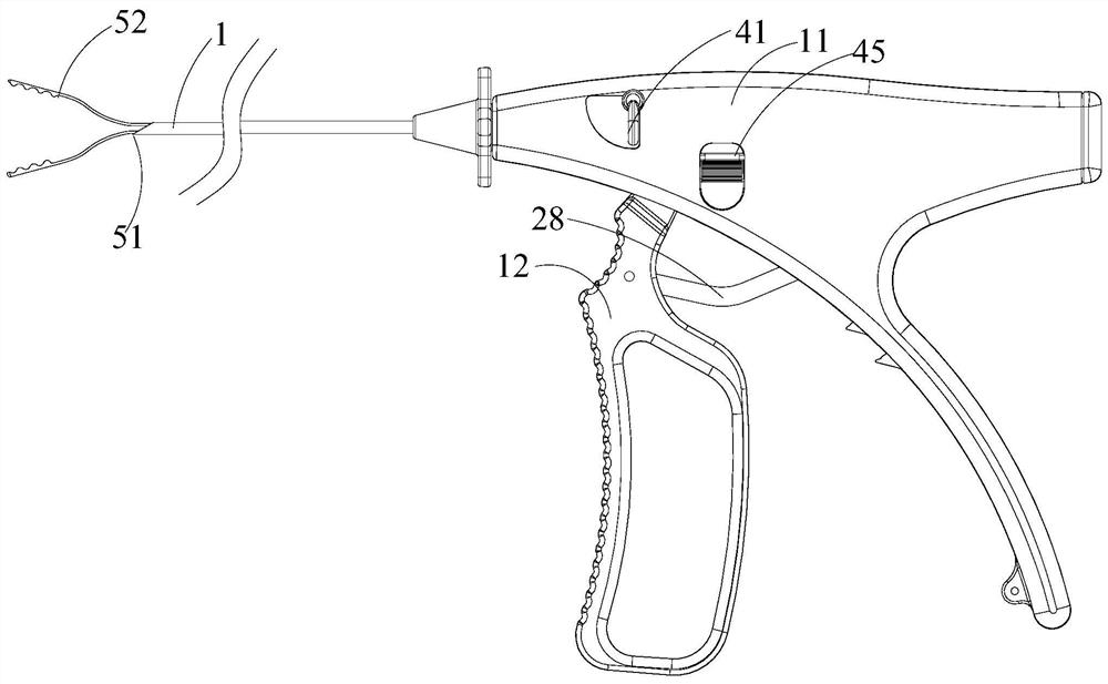
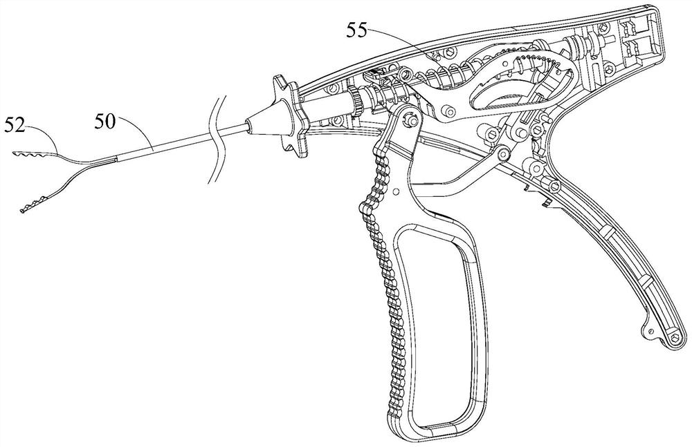
[0071] see Figure 1 to Figure 16 As shown, the present embodiment provides a puncture forceps, comprising: a body 11, a pliers rod 1 matched with the body 11, and a movable handle 12; Rotation fit, so that the movable handle 12 can rotate relative to the device body 11 under the pinching action of the hand of the medical staff. The pliers rod 1 here has a hollow accommodating cavity passing through both ends in the axial direction, and a pliers body 50 adapted to move axially relative to the pliers rod 1 runs through the accommodating cavity; and one end of the pliers rod 1 away from the body 11 It has a cone tip 51; one end of the pliers body 50 adapted to protrude from the cone tip 51 is provided with a pair of pliers wings 52 suitable for opening.
[0072] Considering the convenience of processing and the smoothness of use, the pair of pliers wings 52 and the pliers body 50 of this embodiment are integrally processed and formed.
[0073] It should be noted that, in an op...
Embodiment 2
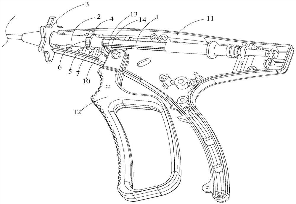
[0095] see Figure 7 to Figure 12 As shown, on the basis of the puncture forceps of the embodiment 1, the puncture forceps of the present embodiment also includes a drive structure for the axial movement of the pliers rod 1 that is matched with the pliers rod 1, including: a push rod 21, a movable mechanism arranged on the push rod 21, The pin 26 , the locking piece suitable for cooperating with the movable pin 26 , and the spring body 55 sleeved on the pliers rod 1 .
[0096] Next, first, putter 21:
[0097] Push rod 21, which is suitable for pushing the pliers rod 1 of the medical device; one end of the push rod 21 is provided with a toggle for pushing the pliers rod 1, and the end of the push rod 21 away from the push head is hinged with the movable handle 12 of the medical device Cooperate. The push rod 21 is rotationally fitted with the device body 11 through the first connecting pin shaft 22, that is to say, the driving action on the push rod 21 can be generated during...
Embodiment 3
[0116] see Figure 7 to Figure 12 As shown, on the basis of the puncture forceps in Embodiment 2, the driving structure of the puncture forceps provided in this embodiment further includes a driving rod 42 connected to the side end surface of each locking piece 30 away from the forceps rod 1 ; And on the side wall of the body 11 is provided with a waist-shaped movable groove 43 suitable for the driving rod 42 to pass through; Here, the setting of the shifting block 45 is convenient for the hand of the medical staff to exert force on the shifting lever 42 .
[0117] Because in the process that the movable pin 26 rotates along with the push rod 21, the locking teeth contact the movable pin 26 before the locking opening 31, that is to say, the locking opening 31 corresponds to the movable pin 26 relative to the locking teeth. The rotation range is larger, and for the locking port 31, it corresponds to the special situation that a pair of pincer wings 52 are completely folded in ...
PUM
 Abstract
Description
Claims
Application Information
 - R&D Engineer
- R&D Manager
- IP Professional
- Industry Leading Data Capabilities
- Powerful AI technology
- Patent DNA Extraction
Browse by: Latest US Patents, China's latest patents, Technical Efficacy Thesaurus, Application Domain, Technology Topic, Popular Technical Reports.
© 2024 PatSnap. All rights reserved.Legal|Privacy policy|Modern Slavery Act Transparency Statement|Sitemap|About US| Contact US: help@patsnap.com