Comprehensive system suitable for full underground water plant

An integrated system, underground technology, applied in the field of integrated systems, can solve the problems of increasing electric lighting in underground areas, high drainage difficulty, and high lighting energy consumption, achieve rational optimization of overall layout, reduce scattered lighting wells, and optimize air supply and exhaust systems. Effect

Pending Publication Date: 2020-09-08
北京信通碧水再生水有限公司 +1
View PDF1 Cites 1 Cited by
  • Summary
  • Abstract
  • Description
  • Claims
  • Application Information

AI Technical Summary

Problems solved by technology

[0004] 1. The workshop has defects of insufficient light and poor ventilation
[0005] 2. The degree of integration between the underground sewage treatment area and the ground landscape park is low
At present, the underground areas of fully underground reclaimed water or sewage treatment plants in my country are sewage treatment facilities, and the aboveground areas are mostly ecological landscape parks. The auxiliary buildings of fully underground reclaimed water plants or sewage treatment plants protruding from the ground, such as stairwells and air wells, are more complex. Many, in order to improve the lighting of the whole underground sewage treatment plant, the usual method is to increase the electric lighting of the underground area, or set up a single lighting patio in the local area. The overall layout of the ground park has a great impact
[0006] 3. There are a large number of stairwells on the ground, which will cause great damage to the overall layout of the ground landscape. A large number of air shafts protruding from the ground also become a restrictive factor affecting the beauty of the ground landscape, reducing the space utilization rate and high cost
[0007] 4. The building layout is unreasonable, which increases the cost of the whole underground sewage treatment plant
Each fire compartment has more than 2 stairwells leading to the ground, adding a large number of mechanical fan shafts, all of which increase the partition wall of the underground production area in disguise, block the underground space, make the underground space fragmented, and cause daily difficult to maintain
[0008] 5. The drainage problem of the all-underground sewage treatment plant is extremely prominent
According to the standard requirements and traditional design ideas, the roof of the factory area is a large-area overall roof, with a large drainage confluence area and high drainage difficulty. The saturated water will soak the root system of the plants, which will inevitably affect the landscape effect of the ground park
[0009] 6. The traditionally designed landscape water glass channel is only suitable for the improvement of the ground landscape effect, and cannot be organically combined with the roof drainage, underground heating and ventilation and fire protection of the fully underground sewage treatment plant
[0010] 7. High energy consumption for lighting
[0012] Patent document CN207620450U discloses a double-layer covered semi-underground sewage treatment plant arrangement structure, including a sewage treatment pool set in the soil layer below the ground, an overhead layer set above the ground, and a recreational facility on the elevated layer. area; all or most of the sewage treatment pool is located below the ground level, and a first layer of coverage area is set between the sewage treatment pool and the overhead layer, and the first layer of coverage area separates the overhead layer from the sewage treatment pool; A second-layer coverage area is set between the leisure area and the overhead floor, which separates the leisure area from the overhead floor, but the design still needs to design multiple stairwells as a safety precaution according to the fire prevention code for architectural design. outlets, reducing the effective utilization of building space

Method used


Image

  • Comprehensive system suitable for full underground water plant
  • Comprehensive system suitable for full underground water plant
  • Comprehensive system suitable for full underground water plant

Examples


Embodiment Construction

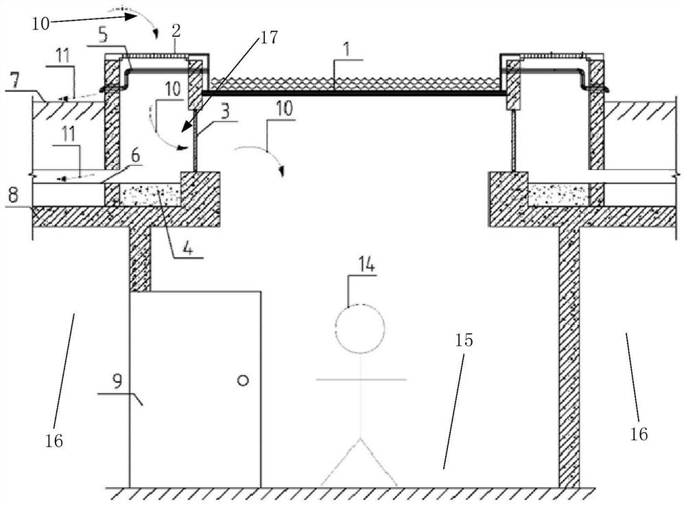
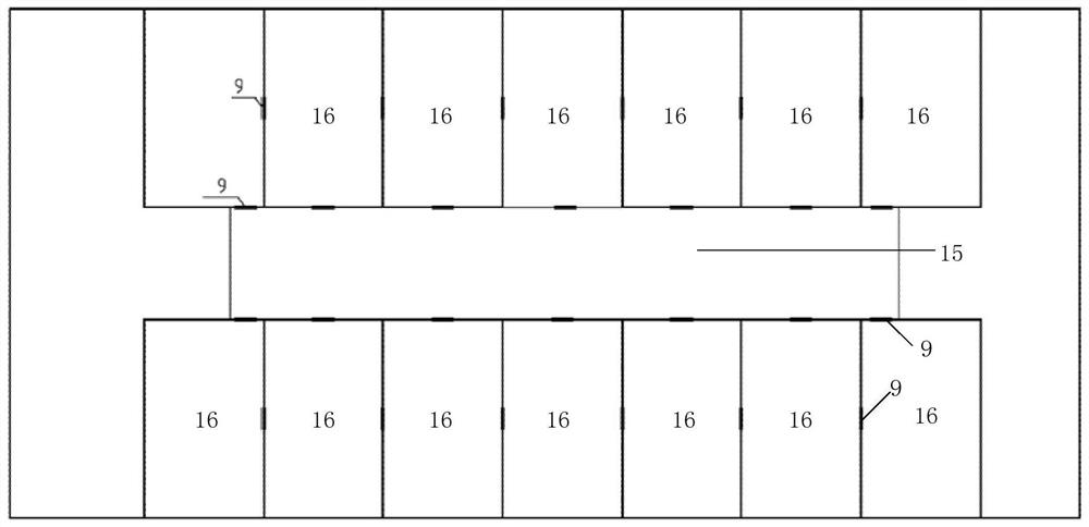
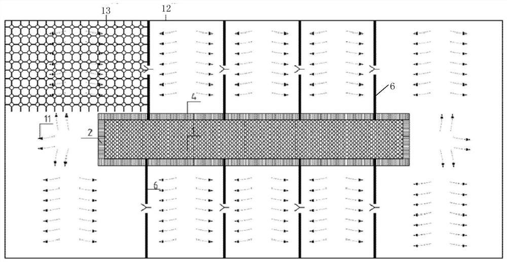
[0052] The present invention will be described in detail below in conjunction with specific embodiments. The following examples will help those skilled in the art to further understand the present invention, but do not limit the present invention in any form. It should be noted that for those of ordinary skill in the art, several changes and improvements can be made without departing from the concept of the present invention. These all belong to the protection scope of the present invention.

[0053] In order to solve the lighting, heating, ventilation, landscape, drainage and other issues of the all-underground water plant, and to meet the requirements of the fire protection code, other professional content is integrated to form a comprehensive system that integrates the sunken square in the architectural form Combining the structure of 15 with the structure of an underground water plant, the present invention provides a comprehensive system suitable for all underground water p...


PUM


Abstract

The invention provides a comprehensive system suitable for a full underground water plant. The comprehensive system comprises a sunken square and a plurality of water plant subareas, and each water plant subarea communicates with the sunken square; the sunken square is provided with a light transmission system, a ventilation system and a water dredging system; and the light transmission system isarranged at the top of the sunken square, the water dredging system is arranged along the circumferential direction of the sunken square, and the ventilation system enables outside air to be supplemented to the water plant subareas through the sunken square. According to the comprehensive system suitable for the full underground water plant, the sunken square is additionally arranged, and a watertank is organically combined with the full underground water plant to form an organic ecological complex, so that the number of floor staircases is effectively reduced by about 50%, the number of airshafts is reduced, the construction cost is greatly reduced, the construction space is saved, an air supply and exhaust system is optimized, integrated layout of ground landscape is achieved, and thelandscape effect is significantly improved.

Description

Technical field [0001] The present invention relates to the field of fixed buildings, in particular to a comprehensive system suitable for all underground water plants. Background technique [0002] With the continuous development of my country’s economy, people’s requirements for the environment are getting higher and higher. In order to improve the current situation of water pollution, my country has invested in the construction of a large number of sewage treatment plants in recent years. The process composition and construction scale are different, but in the construction mode Above ground, most of the reclaimed water plants or sewage treatment plants are above ground. Above-ground sewage treatment plants have the advantages of good ventilation and sufficient light. However, the construction of above-ground sewage treatment plants will cause waste of land resources and environmental pollution on the one hand, and on the other hand will cause the depreciation of surrounding lan...

Claims


Application Information

Patent Timeline
Patent Type & Authority Applications(China)
IPC IPC(8): E04H5/02E03F1/00E03F3/02E03F5/18F24F7/007F24F13/08F21S11/00A62C3/00
CPCA62C3/00E03F1/002E03F3/02E03F5/18E04H5/02F21S11/007F24F7/007F24F13/08
Inventor 安东侯锋邵彦青彭轶陈浩林杨茂东陈曦韩颖段更月
Owner 北京信通碧水再生水有限公司
Why Eureka
Try Eureka