


Quick Research
Generate reliable direction feasibility study reports for your R&D in just a few steps.

Technical Q&A
Discover and master advanced knowledge NOW. Basics, ideas, possibilities, all at once.

Find Solutions
As an expert in R&D theories, this can generate solutions to your technical problems instantly.

Evaluate Feasibility
Analyze your overall solution with one click, know your potential R&D risks in advance.

Monitor Landscape
Get weekly tech updates, stay abreast of the latest tech innovations and key insights.
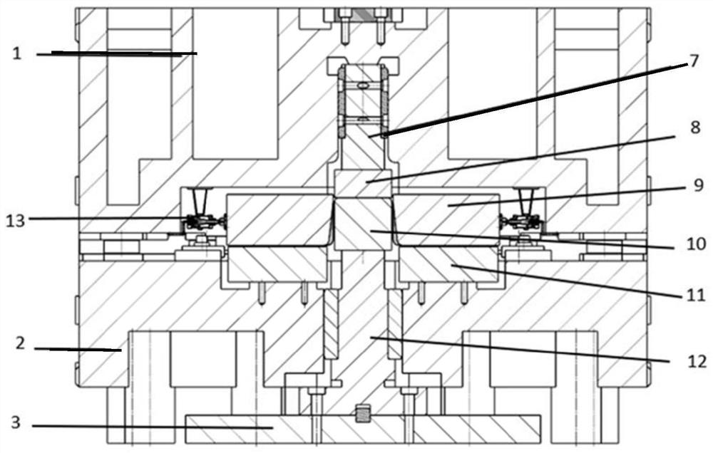
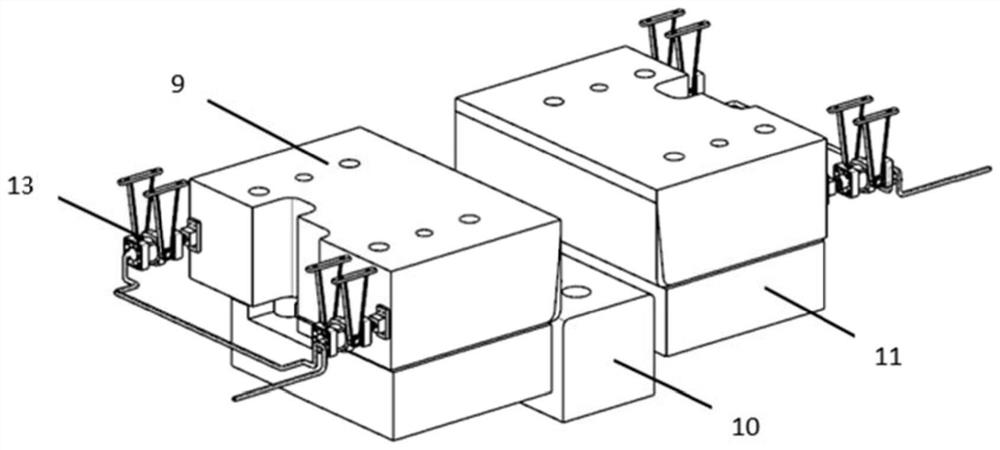
A die structure for plate springback experiments that can switch between multiple stamping processes
A mold and plate technology, which is applied in the field of mold structure for plate springback experiments, can solve the problems of increasing the difficulty of plate stamping springback experiments, prolonging the total cycle of mold processing and manufacturing, increasing mold design and manufacturing costs, and shortening the production cycle. , saving production cost, simple structure effect
- Summary
- Abstract
- Description
- Claims
- Application Information
AI Technical Summary
Problems solved by technology
Method used
Image


Examples
Embodiment Construction
[0043]In order to enable those skilled in the art to better understand the technical solutions of the present application, the present invention will be further described in detail below in conjunction with specific embodiments and accompanying drawings.
[0044] The orientation terms such as up, down, left, right, front and rear in this application document are established based on the positional relationship shown in the drawings. If the drawings are different, the corresponding positional relationship may also change accordingly, so this should not be understood as limiting the scope of protection.
[0045] In the present invention, the terms "installation", "connection", "connection", "connection", "fixation" and so on should be understood in a broad sense, for example, it can be a fixed connection, a detachable connection, or an integrated Connection can also be mechanical connection, electrical connection or mutual communication, direct connection or indirect connection ...
PUM
 Abstract
Description
Claims
Application Information
 - R&D Engineer
- R&D Manager
- IP Professional
- Industry Leading Data Capabilities
- Powerful AI technology
- Patent DNA Extraction
Browse by: Latest US Patents, China's latest patents, Technical Efficacy Thesaurus, Application Domain, Technology Topic, Popular Technical Reports.
© 2024 PatSnap. All rights reserved.Legal|Privacy policy|Modern Slavery Act Transparency Statement|Sitemap|About US| Contact US: help@patsnap.com